
I'm a paragraph. Click here to add your own text and edit me. It's easy.

Laying the Track
Module: 13
Laying the Track
Once you feel comfortable having finalised the overall layout design and constructed the roadbed for your railway it's time to actually lay some track. Please note that this module is best read in conjunction with Module 11: Choosing the Track.
After all the hard, preparatory work you might say that the fun really begins.
Assuming that all the steps to this point have been methodically carried out to a satisfactory standard the process should not prove unduly challenging.
Whilst the procedures for laying track are more or less the same whether you elect to use sectional track, flexible track or build your own you will still find wide variations in the methods used with each solution having its strong advocates.
General Advice on Track Laying
Importance of Track Laying
The key to laying track that is dependable and long-lasting, and thus ensure operational reliability, is to observe a few general guidelines evolved by experts in the field based on years of experience.
-
Take your time. Don’t try and rush things. Always ensure that track is perfectly straight where it needs to be and that any curves are free of kinks or doglegs which will always have a detrimental impact on running your trains.
-
Make sure that each section of track is level from side to side and end to end taking account of any intended grade or superelevation (see later). It is always a good idea to use a long straight edge as a guide. Get down low and place your eye as close to the railheads as possible to help detect any inconsistency.
-
Allow sufficient spacing between the track and any potential lineside obstruction or any adjacent running track (see Clearances).
-
Don’t forget to check for vertical clearances if you plan to install any tunnels, signals, bridges and viaducts, etc.
-
Ensure that all joints, whether soldered, crimped or screw terminal) are tight and lubricated with conductive paste (see below) to safeguard against loss of electrical conductivity.
-
If you possess a track gauge remember to use it often.
The importance of good track laying cannot be emphasised enough.
First, it is important to recognise that time consumed in laying your track to a high standard is always well spent. As stressed above, never attempt to rush the process or operational reliability will suffer and you will be constantly going back over your work in an effort to identify what is causing poor running or derailments.
Make sure you have your scale track plan conveniently to hand, preferably encased in an A4 polythene or acetate cover sleeve to protect it from the environment. Otherwise it will soon be covered in mud and fingerprints once you are on site.
This does not mean that you should necessarily follow your track diagram too slavishly. Nothing is set in concrete at this stage and it is often preferable to adjust things to accommodate a change of mind than stick too rigidly to your plan and have a face the prospect of even greater upheaval at a later stage.

When you can see the track in situ you may well feel that it would look better if you move things about a bit to improve the aesthetic flow of the line or improve operability even if this means adjusting your roadbed.
With this plan as your guide start to lay out your sectional track on the prepared roadbed – you don’t have to connect it all up – this is more of a scoping exercise to make sure that you are happy with your layout design and that it will all fit in the designated area.
Nothing is set in stone at this stage. It can be far harder to change the plan later on so, once again, don’t rush things. Take your time to ‘play around’ with various designs before making up your mind. You don’t even need to join the track together at this stage, just lay it temporarily in position and see if it looks right. The main aim is to see that everything fits the available space (allowing for any buildings or scenic features) and that your trains will look good travelling along the intended route. Will they behave in a prototypical manner if this is what you are after and fulfil your chosen theme or concept discussed in Module 5.
If you intend to use flexible track this provisional ‘scoping’ exercise will prove more challenging but probably still worth the effort.
Some modellers prefer to ‘loose lay’ the track for the entire layout to gain an overall impression of how it will look whilst others address each section in turn before moving on to the next one. If you are building a large layout the latter approach may be unavoidable, especially if there is a sudden change in the weather. There is no ‘right’ or ‘wrong’ way so just experiment and adopt whichever method suits you personally.
Also remember where the main scenic features are going and check whether the space is adequate without compromising the actual tracks and railway ‘furniture’.
Points
Take special care to position points (turnouts, switches), preferably on a level surface, and make certain that they can be operated successfully either manually or using some form of remote control. Also check whether there will be adequate clearances in all directions to eliminate the chance of collisions or damage – especially under bridges and through tunnels.
Apart from the different approaches in laying flexible track as compared with pre-formed sections there is little difference in the treatment of different types of track whatever the code, rail or sleeper arrangement.
Finer scales need more careful handling at every stage but generally the methods are much the same.
Once you have provisionally laid out your track to your satisfaction
(and moved any relevant foundations or track-bed if the route has
changed) start connecting the pieces together. Ensure that each
piece of track is carefully positioned next to its neighbour and that
the track is as straight and level as you can possibly make it. Use
a spirit level to check the surfaces are perfectly level and correctly
aligned in all directions.
On inclines (grades) or when installing banked curves this is not
always easy but time spent now will save frustration and much
heartache later.
Frequently look along the track from a low angle to see if there
are any bends or kinks which will be clearly visible, however slight,
and spoil the appearance of your layout if not attended to.
Sectional Track
Sectional tracks are designed for indoor and outdoor use and simply push together using slide-in rail joiners. Some different brands will also connect with each other provided they have the same rail profile e.g. Code 332.
Makes such as Aristo-craft, USA Trains, and Bachmann Brass also have additional lateral "locking" screws in their joiners to hold the track together more firmly in alignment. These minute hexagonal 2mm screws are normally located beneath the track in a blob of "goo" but Bachmann fit them to the actual rail end which means that you have to remove them before joining adjacent track sections together. You can also buy plastic track clips which grip the underside of the ties / sleepers and help to prevent the track from pulling apart, but these are rarely used outdoors.
Incidentally, I have found that Piko Brass Rail Joiners provide a very snug and secure joint – much tighter than any other brand I have used. I would be interested to learn whether other garden railway builders also find this to be the case.
Some proprietary brands, such as Bachmann Rolled Steel track are entirely proprietary and will not join with any other track being only compatible with each other. As the Bachmann range is decidedly limited and unsuitable for use in the garden it should be avoided in the majority of cases.
Apart from the fact that they lack flexibility, sectional track is little different to flexible track, which is often manufactured using identical components.
In fact, it is possible to induce a little ‘flex’ into the track by cutting through some of the plastic links on the sleeper strip. This can be useful if you need You cannot easily reverse this process so be careful before you attempt any physical modifications.

A rare example of an LGB 14805 Nickel Plated Right Hand Manual Switch/ Point long discontinued.
Flexible Track
Flexible track (Flexitrack) has already been mentioned previously in this guide and many large scale modellers now use little else although some choose the middle ground by using sectional track for the straight runs.
In the larger gauges the term” flexible” is something of a misnomer since it is not really that flexible at all. However, it is certainly more versatile than fixed sections and can be used to create smooth wide radius curves easing perfectly into straight track.


“Ready-Made” Flexible track is normally supplied in completed sections between 3’ and 6’ long and incorporate plastic sleeper or tie strips which have a bit of lateral give allowing the track to be bent into a curve. The amount of elasticity will vary depending on the manufacturer, the manner in which the sleeper strips are conjoined, the code (size) of the rail and the material form which the rail is made.
The term “ready-made” is somewhat disingenuous as if you use a single rail bender (see below) you will have to dismantle the track completely to separate the rails for bending.
Rail Benders
The cross-section of brass rail in large scale (particularly Code 332) is much thicker than found in smaller scales and is far more difficult to bend satisfactorily as it tends to spring back into its original shape.
In order to overcome this tendency, it is recommended that you use special tools made for the purpose and known, not surprisingly, as “railbenders”. These usually incorporate a number of wheels (usually three in number – two of which act, more or less, as guide wheels and the third adjustable wheel which actually bends the rail to the required radius by the application of gentle force) which gently curve the rail as it is pulled through the rollers. If you try and do this by hand you are likely to end up with rail that is kinked or skewed and as brass rail costs a fortune the cost of mistakes can soon mount up.
Notwithstanding the initial outlay on a good railbender it is well worth the investment as flexible track offers a number of advantages:
-
You can be far more latitude in your track designs when not constrained by pre-formed fixed radius curves and create broad sweeping bends more typical of those found on a full-size railway.
-
It gives you more freedom to adapt your track design should it prove necessary rather than simply conform to the limitations of fixed radius curves.
-
Easements and transitions are far easier to lay than with fixed curves.
-
Longer rail lengths entail fewer joins and less risk of poor connectivity.
-
Flexible track can sometimes work out cheaper than extra-large radius curves.
-
Since you only need to purchase flexible track and points to meet most layout requirements you don’t have the problem of calculating the precise number of track sections you need to complete your railroad.
Some rail bending machines are illustrated in the next gallery and whilst production of most of these machines has been discontinued in recent years, you may still find second-hand examples available:

Describe your image


Describe your image
This video originally submitted by Large Scale Online (USA) reviews the Train-Li Easy Duo Rail Bender which is still available direct from Train-Li. Unfortunately LSOL are no more and failed to make their repository of data (much of it contributed by website users) available for future generations. This video seems to have survived. There was a rumour that a DVD had been made available of the company's databank but so far I have been unable to trace same. If you have a copy please let me know.
This second video from Garden Trains reviews the Aristo-craft Duo Track Rail Bender which is still available direct from Train-Li. Please note that this is an archive video that was create before HiDef was available,
Yet another video extolling the merits of the Aristo-craft Dual Rail Bender - no longer available from the company itself which ceased business at the end of 2013. Their demise is a great loss to the large-scale model railroad fraternity. Note the innovative track ties to save you the job of cutting through some of the tie sections.
Now you may notice some similarities between the Aristo-craft product and the newer Train-Li rail bender. One would expect the original design to have been heavily patented so perhaps the same third-party manufacturer is involved? You may also wonder why I have not included reviews of other manufacturers products in a "Which" style best buy survey. It is not as if I have not tried to do so but it is as if the entire large-scale customer base has adopted the Train-Li Easy Duo as the only mass-produced dual rail solution still in production. The majority of the competing products appear to have been discontinued for one reason or another.
Perhaps, as Paul D. Race, the esteemed contributor to Family Garden Trains observed, "this is the best thing since sliced bread". You can read his updated and authorative article using the link below.
The only survivor is the single railbender category is the device sold by Sunset Valley Railroad pictured here and hopefully still available from their online store (link below) although it is not entirely sure that this product is still in production.

Always chose the best quality rail bender that you can afford to form your curves using Code 332 rail. It is tempting to save money by using your hands or body but nearly always a mistake when you end up with a pile of unusable ‘kinked’ rail (see Module 10: Choosing the Track for more details). If you adopt this method, as pointed out earlier, you may need to remove any plastic sleeper (tie) strips and thread them back on again when the rail is formed to the correct radius. This can be painstaking but it is possible to purchase rail and sleeper sections separately and only have to perform this task once.

Some Rail Benders (such as the Dual Rail Bender) allow you to bend both rails at once whilst keeping everything in situ but invariably incur a cost penalty for the convenience.
For wide radius curves you may even be able to persuade the track to bend to the required radius by simply removing the narrow plastic connection strips linking the sleepers (ties) on the inside of the curve. In fact, this is a useful dodge for creating straight sections from surplus Radius 1 curved sections which can often be acquired ‘for a song’. Note:1
Note.1: the phrase, still in vogue with many’ old geezers’ as a metaphor for virtually nothing or a very small or trifling amount is said to have originated in Elizabethan times when street entertainers would perform a song in return for a penny or two. With inflation this is probably enough to buy a house these days.
The most frustrating and fiddly aspect of building flexible track is usually feeding the rails through the sleeper strip chairs or tabs. Considerable patience is required. It is advisable to slide both rails on simultaneously if possible, and use a firm surface to support the ties whilst doing so. The more you do the better your technique will become but try not to tackle too many lengths at one time to avoid undue stress.
Push the sleeper strips from the end of the rails to the middle of the track assembly and add additional strips to that side until it is half-complete. Then do the same from the other end.
TIP: One tip I've read about is to wrap a rubber band tightly around the rail ends when 'feeding' rail through the ties to keep the latter from slipping off while you handle the track. It will also be easier to slide in the rail if you spray the plastic web chairs with WD40 or similar graphite-based lubrication beforehand.
TIP: Another hint for threading on plastic sleepers is to lightly chamfer the edges of the rail at both ends with a file this creating a ‘lead’ on for the chairs to be gently eased onto the rail – half from one end and the other half from the opposite end. It is a certainly a time-consuming and laborious job but sometimes perfection takes a little longer.
Cutting Rails
When cutting rail always support the material on a firm surface and use a fine tooth razor hobby saw to make a clean vertical cut. If you cut at an angle you will not achieve a good joint. Finish off the rail profile by removing any burrs using a jewellers rectangular file. You might also find a mitre cutting block to simplify the task but it is not always possible to align the mitre with the rail profile.

.jpg)
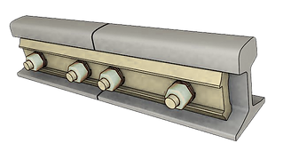
Bachmann Brass Rail Joiners
The most popular way to join adjacent rails together is to use brass rail joiners specifically made for the purpose. Pre-formed track sections will normally come already fitted with a brass rail joiner at each end. Unfortunately, on many brands, this tends to produce a noticeable, some would say unsightly, gap between adjacent track sections.
I understand that any 'rivet' impressions on a fishplate joiner should face outwards but can find no evidence for this tip.
In order to prevent the movement of the joiner tightly crimp it to both the inside and outside web of the rail with flat or needle nose pliers. Neither of the above measures will eliminate voltage drop due to the thin cross section and lower conductivity of the rail joiner compared to brass rail or a thick copper wire. For this reason, you should also consider using the alternative methods already mentioned in a previous module to overcome the dreaded ‘voltage drop’ including rail clamps or wire jumpers (see below).
Note: In railway terminology, a fishplate, splice bar or joint bar is a metal bar that is bolted to the ends of two rails to join them together in a track. The name is derived from fish, a metal or wooden plate bolted to each of two timbers that have been butted or lapped together such as a ship's mast.
In the case of flexible track, you will need to cut one or possibly two sleepers / ties for the sleeper strip to accommodate the joiner. On occasion it can prove difficult to feed the joiner on to the end of the rail. If so carefully open up the mouth of the joiner with a small screwdriver or similar tool, insert the rail joiner and then crimp tightly to the rail with suitable pliers. You can also try tapering the rail end with a file.
Soldering
For many garden railway modellers, the ultimate ambition is continuous and fault-free rail to achieve perfect running. With this aim in view, you might contemplate soldering all rail joints to ensure proper alignment and ensure optimum electrical conductivity. The possible downside is that in very hot weather (and bearing in mind the effects of climate change) the absence of any room for joint expansion could cause the trackwork to buckle. If you live in a moderate climate the chances are that you will not experience this to any degree, particularly if the track is "loose laid" and free to move. Another disadvantage is that any neat soldering must be un-soldered if you need to make any subsequent changes to the layout (often inevitable).
There is certainly still a school of thought that maintains that all rail joints must be soldered. Soldering rail joints is not too difficult to accomplish using a small, hand-held butane torch provided safety precautions are observed. According to Marc Horovitz (until quite recently the Editor of Garden Railways Magazine), the secret is to make certain that the rail ends are scrupulously clean and to apply a lot of heat to the joint as fast as possible to ensure that the solder flows correctly.
Brass rail tends to absorb heat very fast so you also have to take care to sure that the excess high temperature does not transfer to the adjacent sleepers (ties, turnouts) and melt them. Marc suggests wet towels, paper or ballast to minimise any melting although any occasional blemishes can usually be hidden by the ballast.
He also advises just using "jumper wires" on the points (switches) in case they have to be replaced in which case they can easily be removed by simply snipping the wires. A lot less hassle than having to remove the solder.
For advice on soldering techniques for large-scale railroads please follow the link below:
Rail Clamps
A third tried and tested solution is the use of proprietary rail clamps as covered in Module 11: Choosing the Track. In addition to providing good electrical conductivity they help to keep the track in alignment. They are quite sturdy and can spoil the look of the line but many garden rail enthusiasts swear by them. The clamps themselves can also involve a significant outlay if you have a large run of track although you can sometimes purchase them in bulk for between £1 - £2 each. Suppliers include Piko, Split Jaw and San-val. Unfortunately the popular Hillman Rail Clamps are no longer in production. Split Jaw rail clamps are probably the nearest equivalent.
For a comparison of the relative merits of clamps visit DCC Wiki by clicking the button below:
San Val Rail Joiner


This Youtube video from USA retailer "TrainLi" may also be of interest:
This explanatory Youtube video from Piko USA explains the merits of their range of clamps
Not so much a video on how to install rail joiners but how to remove them. I am not entirely convinced this approach will work every time but make of it what you will:
Fixing the Track
Whether to fix the track in place or not is another choice facing the outdoor large-scale modeller and as usual there are often opposing bodies of thought as to the best method. Some argue that the track itself should be relatively free to move, expand and contract according to the seasons, and thus minimising the possibility of rails and track-base buckling (just like the prototype) whilst others favour fixing it firmly in place at regular intervals.
It may also be necessary to lightly pin (to a wooden base) or glue your ‘flexed’ track into place on the roadbed to avoid its natural tendency to spring back into its original state. This may also prove necessary on pre-formed track sections if you want them to stay firmly in place. When pinning your track to a roadbed, even temporarily, always nail the ends of a sleeper (tie). If you pin in the middle (which would seem the logical place as many manufacturers provide pre-drilled holes for the specific purpose) any warm sunshine may cause the track base to flex at the ends - this distortion can be difficult to rectify.
Naturally, there are even differing views as to the best fixing method to use.
Pinning is often preferred by enthusiasts who want their track to be able to move slightly in hot weather and whilst relatively simple if your trackbed happens to be made of wood it is not quite so easy if you have elected to use concrete breeze blocks.
Probably the simplest solution is to use adhesive. Once again there are differing views as to the best fixative for the purpose but diluted PVA wood glue with a few drops of washing up liquid to assist the flow and absorption is popular but make sure that you use the EXTERIOR version of PVA if you want it to last.
If using PVA based adhesives to fix your outdoor track make sure it is the external weatherproof formula .
It is preferable to use a dispenser or pipette to drop the solution between sleepers and allow it to run underneath. Be sure to clean off any spillage on the rails and take care not to get any glue on the points or it may cause problems later.
If you are not ballasting or are using flexible track it may be necessary to lightly pin the track down to keep it in place. Whilst manufacturers will often incorporate pre-drilled holes in the centre of some of the sleepers / ties in order to simplify the task. However, there is a concern that pinning along the centre-line may cause the track to bend upwards at each end during very hot weather. One way to reduce the risk is to pin through alternate ends of these sleepers.
If you prefer a more secure fixing a combination of pins and adhesive may be the answer or even consider switching pins for proper brass, galvanized or stainless steel screws. It is suggested that you pre-drill the sleepers (ties) first and use small anchors (US) or "rawlplugs" (UK) – other wall plugs are no doubt available. Of course, if you followed the advice in Module 9 you will already have embedded wooden fixing points along the permanent way in which case wall plugs are not necessary.
Most important of all make certain that your trackwork is aligned correctly as it can be difficult to lift and reposition later.
Make sure that your track is in perfect alignment before gluing down as mistakes can be difficult to remedy afterwards.
Laying Flexible Track
The overall trend in the railway modelling community is to use flexible track (flextrack) rather than pre-formed fixed radius sectional track, espacially when realism and smooth flowing curves are a major consideration. There is little doubt that the intrinsic properties of "flextrack" allow for much smoother curves thereby enhancing both the appearance and operational performance compared to the aknowledged shortcomings of rigid sectional track.
As Train-Li point out on their website flextrack enable you to "mould" your layout to the landscape that is already in place rather than trying to carve-out an area in an attempt to recreate a "table top" layout.
The ability to ease flextrack into a wide curve as on the prototype significantly improves operations and also places less strain strain on engines.
If you haven't already read the flexible track section in Module 11 Choosing the Track it could be worth doing so now.
Flexible track tends to come in two forms. Either longer pieces of pre-assembled trackwork (typically 4' - 6' ) which can be 'flexed' to a certain degree, or in component form (rails, sleeper (tie) strips, and rail joiners.)
If you are laying straight track you can use the pre-assembled version as it comes just making sure that any slight bows or distortions are corrected using a straight edge and you eyes. Get as close to ground level However, when it comes to making curves there is a divergence of approach.
Some modellers will remove all the tie strips (sleeper 'webs'), bend the rails to the required radius using a rail bender and then reassemble everything before fitting into place on the layout. Laying flexible track in this manner does not come without its complications. Not only is there the fiddly and time consuming process of diassembly and reassembly but when you bend the track (also a matter of trial and error) the inside rail will always tend to be longer than the outer rail and require cutting (especially to align with sectional track points).
This can be performed either with a fine metal hacksaw or a miniature rotary drill cutter, before attaching rail joiners. Whilst cutting any track take care to ensure that the cut is square as any angle will create a uneven gap at the joint. It is also a sensible precaution to wear protective glasses for this task to avoid the possibility of stray metal fragments damaging your eyes. Don’t spend a lot of money on the latter. I bought one from Lidl as part of set, similar to that featured in this YouTube video, for a very reasonable sum (around £16 as I recall).
The track may also exhibit a latent tendency to spring back to its original straight form which may necessitate fixing to the roadbed in some way to counter this proclivity.
Another school of thought contends that if you solder two or more sections together at every joint at the outset the track becomes progressively more flexible (or perhaps unwieldy) and you can introduce the track into position where it is required quite naturally. Once again the wider the radius the curve the easier this process will tend to be. On the other hand coping with 15 - 18 feet of flexible track can be quite a feat for just two hands and the possibility of kinking the rails is always there.
However, the latter method does save rail. Rather than having to cut off the inevitable rail "ends" on the inside track rail these can be "fed' into the adjacent section as laying progresses thereby offsetting the joins (see "lapped joints" below.)
As far as I have been able to establish, when it comes to track laying, most modellers adopt a more simplistic technique which speeds up the entire process without neccessarily sacrificing too much accuracy and and appearance.
This involves gently easy a complete length into an initial curvature, then snipping away some of the thin plastic "straps" between the inside of the track with nipper pliers. Depending on the degree of curvature required you should only cut every 2nd or 3rd strip initially although for very tight curves (not recommended) you may need to sever all the connection strips. lay the track in place on the layout and gradually ease it into position taking great care not to kink the rails. With practice this should become easier to accomplish.
There are a few more tips on the best way to lay flexible track in Module 11: Choosing the Track
Lapped, Lapping or Staggered Joints

If you can handle the extra inconvenience, you may prefer to use “lapped” or “lapping joints” where the rail joints are positioned along the opposite rails in a staggered pattern (conforming with North American practice) rather than having square joints where fishplates are inserted on both rails adjacent to each other (European practice). This produces a smoother running curve which resists centrifugal force better, achieves uniform vertical continuity of the track and reduces the possibility of kinks forming. This is better illustrated in the adjacent graphic.
This method has the added benefit of maximising the use of rail whilst minimising the number of cuts and leaving you with one final residual length to cut-off as opposed to numerous pieces too small to use.
On the other hand, the reason why staggered joints have not been more widely adopted in other countries is that according to the laws of physics the alternating jolts on opposite sides could set up a rocking motion – a phenomenon apparently known as “harmonic rocking” – which could prove disturbing to rail passengers. As there is more freight traffic in the USA there is less of a problem than in Europe (and model railway passengers are unlikely to complain) but the following video is real “Railroad Rock and Roll”:
“Rockin and Rollin” (literally!) on the Kelowna Pacific Railway (KPR)
I also managed to find another YouTube video entitled “World’s Worst Railroad Track Compilation” which illustrates how bad things could really get is track becomes distorted.
Conductive Paste

One of the many "Copper Grease" formulations available.
I am about to substitute my Massoth Graphite paste with a proprietary Copper Grease "Anti-seize" Compound which is primarily intended for the prevention of break-squeal when applied to disc breaks and calipers. According to the tin the product "ensures excellent protection for metal parts against heat, seizure, rust, corrosion, water and acid. The grease forms a protective coating that will not wash or burn off." This seems to cover all the bases and seems worth trying if only because it is much cheaper than so called 'conductive' pastes.
Indeed, as reported above, it is not entirely clear whether conventional "conductive pastes" supplied for outdoor model railway use materially improve conductivity at all but mainly serve to inhibit the ingress of water and oyygen and are, therfore, more of an "anti-corrosion" paste as one USA railroader described such formulas on the My Large Scale forum.
He had used auto-motive 'grease' on his railroad pike for over 18 years with no problems at all.
Clearances
North American Railroad Clearances
UK Railway Clearance Standards
Another very useful and highly detailed contribution to this topic (and many others) that I came across in my research is kindly published on the web by Rick Blanchard at Urban Eagle who has prepared detailed charts of Standard Dimensions for most popular scales including Gauge #1, 1.29, 1:22.5 and 1:20.3 Fine Scale based on standard USA practice:
At this point I was hoping to cover an equivalent standards guide governing the modelling of UK railway practice. Unfortunately, there no longer appears to be a central standards body who encompass model railway practices as a whole but if there is please let me know. This is a rather sad state of affairs.
Apparently, the UK even refused to co-operate with MOROP in their endeavor to standardise modelling standards across Europe but failed to create an equivalent unifying body with the necessary authority and 'clout' to oversee the hobby in Gt. Britain.
According to Right Lines (a magazine from Gaugemaster) in 1945 an attempt was made by interested parties (including the editors of popular hobby magazines and eminent modellers of the day) to set up just such a body - the British Railway Modelling Standards Bureau (BRMSB) but this proved largely ineffective lacking powerful trade backing and little direct participation by established model railway clubs and societies.
In a series of articles published in 1966 in both the Model Railway Constructor and Model Railway News the 'breakaway' Model Railway Study Group cited BRMSB as actually having a detrimental effect on the adoption of scale modelling standards by permitting excessive deviations and weaknesses.
As Wikipedia observe the globally more-widespread international NEM and NMRA scale standards are relatively unobserved in Great Britain and used almost exclusively by those modelling foreign prototypes. Enthusiasts modelling British railway practices tend to follow the standards set by the representative body for a particular scale e.g. Gauge 0 Guild; G Scale Society; 2mm Association; S Scale Society; 7mm Narrow Gauge Association; 009 Society; etc. There are literally dozens and dozens of local model railway clubs and societies but no central coordinating body as such but if you know of one please let me know
It would seem that we British prefer to ' paddle our own canoe'' and even our isolated adherence to 'Double-0' (00 or 4mm Scale) as the most popular scale when most of the world has adopted the more logical HO (3.5mm Scale) tends to support this argument.
North American Jackson-Sharp Wood Sided Passenger Car
As you can see from these carousel images the 6' nominal clearance between this selection of Bachmann, LGB and Piko Jackson-Sharp passenger cars using minimum Radius 1 curves is alarmingly close and collisions are very likely. (Just click on any image to enlarge.)

These clearances should be always be based on the largest train you envisage intending to run on your railway rather than any train you currently own or initially plan to purchase. This is an area where it is invariably better to allow more rather than insufficient space.

Regardless of which type of track you choose to install always make sure that you have allowed adequate vertical and lateral clearances between your trains and surrounding landscape or lineside structures such as bridges, station platforms, signals, tunnel mouths, etc.
In the UK the distance between the inner rails on double track railway lines varied from *company to company" but was subsequently standardised under British Railways (BR) at around six foot (1.82m), widening on curves (colloquially known as "the six-foot way"). At some point, possibly the 1970's, when wider bodies were introduced this was increased to nearer 6'6" (1.91m).
* According to Mike Smith the former Great Western Railway (GWR) seven foot (2.13m) broad gauge lines had, by far, the most generous clearances in the UK with thirteen foot six inches (4.1m) vertical clearance and nine foot eight inches (2.9m) width at the widest point but this is considered tight by European and American standards.
For prototypical accuracy it should be a relatively simple matter to calculate the clearances between adjacent track which is normally measured between the outside edges of the railheads (but sometimes between rail centres). However, in practice this is likely to prove quite a challenge as there is surprisingly little guidance on the subject.
Firstly, there is a veritable multitude of gauge/scale combinations or standard gauge and narrow gauge implementations in large-scale railways to take into account. This is compounded by the country and era being modelled, the appropriate loading gauge for that era, make of locomotive and rolling stock, and make of track and its particular geometry, together with the nature of the track alignment (single track, adjacent double tracks, high-speed, standard main lines, additional running lines, goods yards, carriage sidings, not to mention presence of station platforms, water towers, loading gauges, yard lamps, signal post, cranes, turntables, etc. etc. Quite a list!
Further consideration also needs to be given to the grade on the track(s), the degree of curvature, the degree of super-elevation, the dimensions of any railway "furniture" adjacent to the track, the list is endless. This is just to establish the lateral clearances required. Vertical clearances are not so difficult to establish but still involve a modicum of guesstimation.
The most useful generic reference to clearance standards is to be found on Wikipedia:
For those of you who already or intend to model according to North American railroad practices there are a number of useful sources but by far the most authoritative is probably the National Model Railroad Association (NMRA) which determines and publishes a whole raft of information and advice on standards, practices, etc. There appears to be a high level of conformance to these standards by American manufacturers.
The most relevant and comprehensive in this context are the NMRA Recommended Practices (RP's) available on their website.
I have incorporated several links to the most pertinent ones below although you may well be interested in perusing many of the others. The calculation for Curved Track described in NMRA RP-7.3 below are so complex that if you model the USA railway practice NMRA even provide an Assistant (RP-7.6) on their website that will calculate the numbers for you using certain parameters - check it out below but don't get your hopes up too high - it is incredibly difficult to complete. Here are the relevant NMRA Recommended Practices: My search for a similar version in the UK proved unsuccessful
European Railway Clearance Standards
As far as the rest of Europe is concerned the principle organisation responsible for ensuring the setting and maintenance of standards in the model railway sphere is MOROP, a mnemonic formed "MOdellbahn (German for model railway) and EuROPe thus keeping everyone happy.
MOROP may have an equivalent calculator but despite having been formed as long ago as 1954 have yet to get around to publishing much of their data in English. (I don't think this has anything to do with the UK leaving the EU - probably just lethargic ineptitude and indifference but that is often the result when experts get together.)
To be on the safe side I would recommend that you allow as much clearance as space will permit in the hope of accommodating the largest locomotive and longest rolling stock you ever anticipate running on your layout.
Bear in mind that a 1:20.3 finescale model steam locomotive such as a Three-Truck Shay, K27 or North American "Big Boy" can be appreciably larger than your average 1.22.5; 1;24; 1:25; 1:29; or 1:32 reproductions even allowing for the tendency for certain manufacturers to practice "selective compression" (sometimes referred to as the 'rubber ruler') when producing their models.
In older publications I have read advice that trains operating on adjacent tracks will clear each other if you allow 5.5" (140mm) clearance between straight tracks and 6.5" (165mm) on curves (measuring from the centre of each adjacent track.) The track geometry employed by Piko uses a 160mm (6.3") clearance between adjacent track centres which appears to bear this out as a company would be surely bound to ensure that its products were compatible with this degree of separation.
Nevertheless, can you be entirely sure as to the actual scale adopted by Piko on their large-scale locomotives and rolling stock? You will notice, just like their competitors, that they do not always reveal this important information in their catalogue. I recall asking Piko Germany this very question about 15 years ago and was informed that the item I was interested in was 'around' 1:27 scale. Their latest catalogue shows that the nominal published scale for Piko equipment is now 1:25 (some would say 1:24) for Narrow Gauge, but 1:29 or possibly 1:27) for standard gauge.
That may not seem very much of a disparity, and probably not worth worrying about, but it indicates that as a general rule their passenger cars, for example, may be much smaller than the equivalent model from Bachmann or LGB (both ostensibly narrow gauge and around 1:22.5 scale). The equivalent Accucraft AMS Cars are in a different league being considerably longer (just like the prototypes.)
All measurements are approximate
In fact, if you compare all four companies iconic Jackson-Sharp Wood Sided Passenger Cars in the table above they are quite dissimilar, and this could make a considerable difference in terms of required clearances. For a start the Piko offerings are way too short at approx. 365mm and only have 7 windows. The equivalent Bachmann "Big Hauler" Cars (1:22.5) are still a little on the short side (possibly "compressed" to 1:24 scale?) and slightly too narrow but at least have 12 windows as do the splendid Accucraft AMS cars.
The dimensions of Bachmann Trains J-S cars are almost an exact match with those from LGB which tends to reinforce the belief that the indigenous manufacturer was eager to compete with the European challenger with a "me-too" look but opted for something a little bit closer to the prototype.
Quite why Piko decided to choose the route they did remains a mystery but probably had to "compress" their design to meet their scale commitments.
Far more interesting than an analytical comparison is to see some photos of all these cars side by side so I have created a series of images (both top and side angle) showing how they compare. Having all 4 car versions myself I think I will probably run them all, but as separate trains, hoping that the contrast in size (certainly length) length will not be too noticeable.
I seem to have gone a little off topic but as you will observe from the foregoing images above the length of a car (and the choice of couplers) does have an appreciable effect on clearances per se. In fact, whatever combination of cars on only a 6" clearance between centers is a recipe for disaster even with the diminutive PIKO coaches.
Let me return to the suggestion that lateral clearances of 5" between centers on straights and 6" between canters on curves are likely to prove adequate. I think that may well possibly have been true in a dim and distant time and could even be valid for many layouts today, but I think it wiser to be on the safe side and enhance these widths - after all nothing is worse than to have devoted many months to building your outdoor layout only to discover that you cannot run some of your prized locomotives or rolling stock on it.
To paraphrase a famous quote "The future is hard to predict. Especially when it concerns the future" by Mark Twain? Nostradamus? Samuel Goldwyn? Anonymous?
It is certainly hazardous to predict the future of Garden Railways. They could fall out of favour altogether or be supplanted by larger, passenger carrying trains, but this seems unlikely with gardens getting smaller due to the prohibitive cost of land and owners lack of willingness to take on the maintenance burden. Who knows?
Nevertheless, the tendency in recent years has been towards greater accuracy and 1:20.3 fine scale which results in larger locomotives and rolling stock such as Bachmann's Spectrum range. In this respect you can 'future-proof' your layout to some extent by easing your clearance just a little bit. If outdoor layouts get smaller you might be able accommodate dual track instead of single.
On my own layout I toyed with the idea of allowing an 8" (203mm) clearance (measured from the centre of the track) should be more than adequate on straight tracks whereas a slightly more generous 9" (229mm) or so (again measured from the centre-line of each track) should be allowed on curves to accommodate the overhang of locomotives or cars as they navigate the section. This is especially desirable where you are modelling 1:20.3 scale.
This translates to a minimum gap of around 6-7" measured between the outside faces of adjacent rail-heads on straight sections and approximately 8-9"between the rails on curves. However, when I examined the track geometry of PIKO G track I discovered that if one used radius 1 (600mm radius) points to create a double track crossover, this will only provide a modest clearance of 6.3"" but this can be expanded to over 10" by using wider radius points (always desirable) viz:
On further reflection, I realised that I would be using the widest radius track I could fit into the available space (and afford) and this decision would necessitate using a mix of LGB and PIKO Radius 5 points (turnouts).
So far, my "Durango Wells & Crystal Springs Railroad" has kept to this dictum apart from sidings by adhering to the 9.5" (240mm) centerline clearance and although I have not yet teste-run all my locomotives and stock I am quietly confident that they should be able to negotiate the line without mishap, even though I have Bachmann Spectrum 1:20.3 Shay, Climax and K27 locomotives in my roster.
I must stress that this is only guidance and if you can test-run a typical consist as you go to be absolutely sure that your trains can safely navigate around the track so much the better.
If your layout will feature tunnels, bridges or other overhead structures you will also need to allow sufficient headroom for your stock to negotiate these potential obstructions without any damage – a minimum of 9” vertical clearance measured from the top of the rail-head to the lowest point of the projected overhang is normally deemed sufficient but many locomotives and some cars are loftier than their counterparts and once again it pays to test any clearances using the stock you plan to run either now or in the future.
You can fix the track in position by pinning to wooden cross-bearers laid in the roadbed, but brass track is heavy enough to be allowed to 'float' in the ballast just like the real thing. There are benefits in doing it this way as the track can extend and contract with the prevailing temperatures.
If you are using a wood track bed it is customary to cover the top in mineralised roofing felt both to protect the timber and represent ballast. This can be quite effective and is relatively cheap and fairly easy to manipulate.
The appearance of most track can look better and last longer if it is ballasted. Ballast is useful in providing adequate drainage and help to ensure that the surrounding soil does not encroach on the line itself (although in practice you will need to get used to constant maintenance in this respect if you wish to keep the soil and garden wilderness at bay).
Code 332 brass track has sufficient mass to behave just like the real thing and will "float" naturally in well laid ballast particles expanding in hot weather and contracting in cold temperatures. Some of the lighter tracks such as Code 250 or containing aluminium rail have less weight and may need additional pinning. This is my personal preference as it closely follows the method utilised on full-size railways.
You also need to allow sufficient clearance between adjacent tracks to avoid collisions. A minimum clearance of 6” – 7” (150mm – 180mm) depending on the type of rolling stock is customary on parallel straight tracks with a slightly more generous 8” – 10” (210mm – 270mm) on dual curved track. These measurements are made from centre to centre of each track and as we have already highlighted should be broadened to accommodate the size of the largest locomotive or piece of rolling stock that you plan to operate on your layout.
As already mentioned the National Model Railroad Association (NMRA) in the USA publish detailed guidance on minimum clearances for all trackside scales and overhead structures including tunnel portals, signals, bridges, etc. on their Recommended Practices for Track Centers & Obstacle Clearances (RP7 in Large Scale.). These clearance standards cover old-time (pre-1920), classic (1920 – 1969) , early modern (1969 – 1983) and modern (post 1983) eras and are rounded to the nearest 1/32”.
Whilst the standards are largely based on the dimensions of USA model trains there seems no reason why they could not be applied to European locomotives and rolling stock which are generally smaller in size.
MOROP (Organization of Model Railroaders and Railway Friends Europe) are in the process of issuing similar NORMS for European modellers but unfortunately the translation process into English seems to be a protracted exercise, I would, therefore, recommend you visit the Gauge 1 Model Railway Association (G1MRA) to ascertain recommended standard dimensions for non-British models (although I still believe the clearances recommended to be too tight so I have decided not to publish them here).
Standard Dimensions of Actual Track Components
The most comprehensive and useful information I have so far unearthed on the subject matter is to be found on Rick Blanchard’s Urban Eagle Website (admittedly relating to American Railroad practice but just as applicable to UK/European modelling).
Voltage Drop
One of the most contentious issues in the hobby (amongst many) is the vexed question of how to minimise voltage drop that can occur the further you travel from the electrical feeds to your layout. Some will recommend that you have several electrical wire feeds to different parts of the layout to "equalise" the current supply. I am certainly no electrical expert but if you think about it the voltage drop on a long length of thin wire must surely be greater than on a thick brass rail section even allowing for the conductivity of copper? I remain unconvinced but you there is no harm in taking precautions providing that your are sure that the extra financial outlay is justified to achieve improved performance.
As you might expect, the greatest potential 'loss' of electrical power is at the end of each rail section where it is joined to an adjacent rail. As Robert Schleicher pointed out in his book "The Large Scale Modelling Handbook" rails are essentially electrical cables as well as the guidance system for your trains and you might well be concerned at the dozens, possibly hundreds of rail joints, every one of which is essentially an electrical "plug and socket". Loose joiners will inevitably be a cause of voltage drop and should be as tight as possible and packed with a conductive grease to give good electrical conductivity. Don't be temptempted to skimp on this grease as it serves to keep dirt and water from working into the rail joiner; prevents oxidation; and also conducts electricity - a triple blessing! Buying conductive grease purposely formulated for outdoor railways can be expensive but you can often find much the same formulation much cheaper in hardware or car accessory outlets.
Let us examine some of the potential solutions:
Enhanced Rail Joiners
The first is what I Iike to call "Enhanced Rail Joiners". As previously mentioned some proprietary track (notably that originating from Aristo-craft, USA Trains and Bachmann) relies on a 'belt and braces' solution of using special joiners incorporating tiny hexagonal stainless steel screws to tighten things up. This can prove quite effective (albeit exceedingly fiddly) and far less unsightly than using large terminal clamps (more later) although the versions available from Split-Jaw (see accompanying image) are possibly less conspicuous than most.

Soldering Joints
There is an equally strong faction who favour eliminating the joiner altogether and soldering every joint in order to create a strong mechanical joint and thereby eliminate electrical problems.
In his book "How to Design & Build Your own Railroad" Jack Verducci strongly advocates soldering your track from the outset except at turnouts. This creates a continuous integrated track with strong mechanical joints. Those who argue against this approach claim that this leaves no room for expansion of the rail in hot weather (and contraction in cold conditions) and will cause the track to buckle even where it is not permanently anchored in position and allowed to float in the ballast.
Jack again challenges this wisdom and claims that the arguments against soldering are weak at best and that it is not necessary to incorporate expansion joints. He maintains that expansion and contraction of the track is handled best by the roadbed with curves expanding slightly on a hot day whilst contracting again when it turns cold. This is why you should never anchor your track but allow it to float free in the ballast.
You will need to read up on the pros and cons involved and decide for yourself. Being hopeless with a soldering myself, this path has never been top of my preferences.

This free guide on soldering techniques is well worth consulting if you have not tried it before (or indeed, tried it unsuccessfully)!


Soldering joints or electrical feeds to weathered or tarnished rail can prove problematic depending on the properties of the metal used. You will probably need to burnish the ends or sides with a miniature rotary wire disk to reveal bright metal without actually damaging it.
When soldering joints, you can still incorporate the odd unsoldered gap providing you solder a jumper wire across the two rails to allow for heat expansion.
A simpler way to achieve much the same result is to solder a short piece of heavy-duty wire (ideally solid single core copper is best) across each rail joint to 'bond' them together (see above). This wire should be 3-4" long and soldered underneath the adjoining rails so as not to interfere with the rail joiners. It can be buried under the ballast if you prefer although it will not be so easy to inspect for damage at a later date.
These ‘jumper wires’ can always be removed at a later date should it prove necessary. How effectively these wires actually perform is dependent on your soldering skills and although many experience modellers swear by this method one cannot help thinking that even a cross-section of a mains wire is far smaller than that of the Code 332 brass rail it cannot be expected to transmit the same current (see Voltage Drop above) but the Laws of Physics are sometimes quite unfathomable.
There are almost certainly other solutions to the controversy but to avoid boring you on the subject I urge you to consult the wealth of published material on the issue and research the many large-scale forums.
%20Jumper%20Wire_JPG.jpg)
Reels of 20 AWG (0.52mm) Jumper Wire - Stranded Copper Wire. (Single Core is often easier to use).
Other colours may well be available and possibly essential if you are seeking to conceal these
wires.
Painting the Track
Some modellers favour painting their trackwork to disguise the ‘plastic look’ and make it look more realistic in appearance. e.g. toning down the shiny brass rail surface, adding oil spills to the sleepers, etc. Make sure to use a paint that is "plastic friendly" and will adhere to, but not interact with, the plastic sleepers. You can use an air brush for this task but they tend to cover up more than intended and you are probably better off using a small paint brush. Whatever method you adopt always wipe off any paint from the top (and ideally the inner edge) of the rails if you intend to use electrical track power.
.jpg)
Image courtesy of Brighton Toy and Model Museum.
Self-Assembled Track
So far, I have not mentioned much about constructing your own self-build or scratchbuilt track as opposed to relying on that commercially available.
This approach entails building and hand laying your own track from whatever material you find most suitable. This “do it yourself” method is quite a different ‘kettle of fish’ Note 2 to using sectional or flexible track and you would be well advised to read up on how to go about it from the experts.
Note 2: Phrase dates from the 19th century when fish kettles were still in common use. In this context it means “a mess or a muddle” as opposed to something previously referred to that is reasonably straightforward.
Way back in the distant past (well pre 1930) it was not unusual for modellers to utilise whatever scrap materials they could get their hands on including old curtain rails and creosoted wood. Scale accuracy and realism were not the principle imperatives in those days and needless to say the end results could look a bit functional and crude to today's enthusiasts.
As the esteemed author C.J Freezer fondly recalls in his Garden Railway Manual (first published in 1995) in the late 1930's Bonds of Euston Road in London (curiously abbreviated to Bonds O'Euston Road ostensibly to attract publicity to its new store) placed adverts in many boy's magazines (see example above) publicising their new low cost track system which employed solid drawn sherardized steel or brass rail (often zinc coated to allay rust), cast-metal chairs and hardwood sleepers. Assembling these components into real railway track would clearly provide endless hours of pleasure and keep the youngsters ‘out of trouble’.
Bond's Ltd., London, UK was founded as long ago as 1887 as Arthur W. Bond. and became a well-known model engineering and model supplies company ten years before Bassett-Lowke Ltd., Leeds and Milbro came on the scene. They also manufactured their own electric and steam powered locomotives and carriages in multiple gauges/scales many examples of which are still around today. Indeed, it is said that their motors and mechanisms had such a high reputation for quality and reliability hat they were sometimes incorporated in other manufacturers products as premium options.
If the idea of 'scratch building' track (especially complex point/switch arrangements) does not instantly appeal to you there are a number of suppliers who can provide you with more the equivalent modern components for assembly into far more realistic trackwork compared to the 'oversize' appearance of LGB Code 332 track.
Suffice it to say that this approach can be very satisfying and give excellent results but can prove a laborious pastime. Be prepared to devote many man-hours (or possibly 'person-hours' in these politically correct days) to the pursuit of excellence.
DIY is not usually recommended for newcomers to the hobby unless you possess the necessary skills or have a tight budget. You will need to undertake research in order to identify the best materials for the purpose and source these from specialised track component or timber suppliers.
It is quite hard to find reference material exclusively devoted to building track for your garden railway but I did come across this interesting article from an Australian modeller who uses aluminium bar for the rails:
More recently I came across this video contribution from the Toy Man who is building some hand-made track in his garage:
The second video in this series concentrates on moulding your own tie-plates:
This third video in the series features the laying of turnouts (points):
This interesting exchange on the subject (which I have paraphrased) is one approach which appeared on G Scale Central which is an excellent free source of material for the G Gauge modeller and highly recommended.
Q1. What would common dimensions be for ties/sleepers i.e. Width, Height, Length?
A. Rick Blanchard has 'standard dimensions' for all things trains on his website:
http://www.urbaneagle.com/data/RRstddims.html
Q2. What code track would you recommend?
A. Rail codes are a matter of personal choice. Narrow Gauge railways were generally lightly built, as they didn't expect Flying Scotsman to come and crush them. So, code 250 rail or even code 215 would work well (and be easier to use than code 332 ed.)
Q3. What rail material would you recommend (I won't be electrifying the layout)?
I used redwood for my ties/sleepers on the homemade track, and outdoor plastic track bases from Llagas for the rest. I actually got bored with plain track, so I just made my own turnouts/switches/points. I used aluminum rails - if you won't be treading on them they are easy to use. Spray them with rust brown primer and sand off the top after you lay the track.
Q4. Are there preferred methods of attaching rails to ties?
A. Stainless Steel spikes are best as they will not rust and will pull out (but can also work loose as a result ed.). Mild Steel will just rust into the wood and you will never get them out.
Q5. What about wood preservation of ties?
A. Using redwood means you don't have to preserve the ties. Cedar is almost as good, but pine or similar will just rot in a few years.
Q6. Any good references for hand spiking track?
There's a long thread on making turnouts, full of esoteric information, on Mylargescale.com. Google "site: mylargescale.com hand turnouts" and you'll get lots of threads.
Some enthusiasts just use whatever is to hand but it does simplify matters if you utilise raw materials and parts specially made for the purpose – especially rail and chairs or possibly ‘GIMP pins’ for attaching the rail to wooden sleepers. You might also decide to purchase ‘ready-made’ points (switches) if scratch building these complex formations is seen as a step too far.
Many modellers, particularly those who model SM32, construct their own track by cutting straight-grained timber to make wooden sleepers. If you are intending to use a lot of these sleepers it is worthwhile building a simple jig to aid cutting (watch those fingers!).
Essentially home-made track is constructed from wooden sleepers cut to length from hardwood square-section (10 - 15 mm cross-section) and then treated with preservative against the elements and other infestations. These can be fixed to longitudinal wooded battens for additional rigidity and ease of alignment.
Commercially available flat-bottom or bullhead rail is then affixed in position on one side using suitable gimp pins, screws, or tiny chairs.
If using the latter you will probably need to slide these on first. The ‘trick’, if you can call it that, is to feed on half the miniature chairs on one end of the rail and then the balance on the other. Repeat the exercise with the second rail before laying and fixing on the other side maintaining a 45 mm distance (or whatever gauge you are modelling) between the faces of the two parallel rails using a track gauge to check for accuracy.
Care needs to be taken when forming into a curved shape and it is common to use a jig for this purpose. The construction of matching point-work incorporating complex frogs and blades is an art in itself and better left to the experts although pre-formed components obtained from specialist suppliers can save you a lot of work.

Kits of Modern Track Components
As mentioned previously, if you are that way inclined, it is quite possible to make your own track (or at least a way of han-laying flexible track to your precise requirements) and several suppliers (such as Tenmille, Sunset Valley Railroad, etc) offer "kits" of parts to make this approach a little easier although it is not one recommended for the average beginner.

Tenmille Components pinned to a roofing felt base to represent ballast.

Tenmille 32mm Narrow Gauge Track Components
A pair of needle nose chain pliers is ideal for driving the spikes if you decide to use them.
Try to ensure that the spike is driven straight down into the sleeper/ ties so that it doesn’t obstruct the one coming from the other side of the rail. The use of safety glasses is also advisable. Allow a small gap (1-2mm) at each rail joiner to allow for any expansion and contraction.

Soldering joints or electrical feeds to weathered or tarnished rail can prove problematic depending on the properties of the metal used. You will probably need to burnish the ends or sides with a miniature rotary wire disk to reveal bright metal without actually damaging it.
Even when soldering joints, you can still incorporate the odd unsoldered gap providing you solder a jumper wire across the two rails to allow for heat expansion.
If you reside in the USA and model in large-scale you are very likely to have heard of Sunset Valley Railroad who have been in business since 1989 and who, in addition to their pre-assembled range of trackwork, also supply components to order. You can 'pick-and-mix' from a wide range of gauges, rail types, tie (sleeper) strips, rail joiners, and clamps. Details of how to assemble these components is to be found on their web page. See also Module 12 : Choosing Your Track.
This is by no means an exhaustive list so please consult Module 12: Choosing Your Track and make your own enquiries.
Once upon a time, individual wooden sleepers would be treated with a tough preservative such as creosote in an effort to proof them again rot. This required immersing the sleepers into a container of the stuff for weeks on end until they were totally saturated and then being left to dry in the open air.
However, creosote is no longer environmentally acceptable and due to concerns over the carcinogenic potential of creosote and coal tar creosote the selling to and use of this substance by the general public is now banned. There are many (more expensive) products now on the market but probably none of them are quite as effective as the original composition.
The choice of rail is entirely up to you and you may elect to go for a finer scale rail ( possibly Code 250 which is more realistic and easily bendable than Code 332.).
Unless you use chairs spiking the rail to the sleepers/ ties is the most time consuming and painstaking part of the process. NMRA standards call for rail to be spiked to at least every fifth tie to give the rail the solidness it needs to hold it in place but I think most would feel safer pinning every sleeper.
When laying the rail keep it centred on the ties at all times. A track gauge is indispensable for this task. Lay one rail at a time spiking at intervals of 8-10 sleepers (ties) and when you are sure that everything is level go back and spike more frequently. Then lay the second rail (either in line or offset if you prefer) using the gauge to obtain the correct gauge using the same method. When the section is complete use the gauge once more to make sure.
It is always a good idea to "loose-lay" your track just to see how it looks and whether there is really the space to accommodate your track plan. If not, it could be a case of 'back to the drawing board' but better this than get three quarters of your track layed only to find that there isn't sufficient room for the station complex.
Lay the track sections in position (as much as you are able) infilling any shallow areas and conversely reducing parts of the roadbed where there are bumps. Sometimes you can just agitate the track slightly to ensure a firm connection with the ballast. When you are satisfied with the result and have checked grades or inclines with a spirit level finish off by applying a further light covering of decorative ballast ensuring that any gaps between the sleepers (ties) and that the sides are filled to bed in the track. It sometimes helps to use a small brush to achieve the desired "worked in" effect and remove any excess ballast.
Make sure that no ballast is high enough to foul the passage of any locomotive or rolling stock paying particular attention to any point blades. In areas where there is a possibility of disturbance, say from animals, garden leaf vacuuming or strimming it is often worth spraying the ballast with a diluted PVA glue solution (adding a few drops of your favourite washing-up liquid) to stabilise the ballast as much as possible. It is generally advisable to use a small spirit level to make sure the track is just that. Nothing should be higher than the bottom of the rail.]
When you come to fixing the electrical feed(s) to the track from your control equipment you have a number of options. You could just rely on a simple solder joint but if your soldering skills are anything like mine it is probably better to use some form of proprietary commercial connector or clamp to ensure a strong connection and good electrical conductivity. LGB and PIKO make excellent brass connecting clamps (virtually indistinguishable from each other) which incorporate colour-coded wires that are independently fed to each rail and screwed tightly into position using a 'Pozidrive' screwdriver. You can also use brass rail clamps similar to those used at rail joints described above. Accucraft AMS rail power connector clamps are particularly well suited for Code 332 rail section.
Preservatives
Checking Track Tolerances
Fixing the Power Leads to the Track
Choice of Rail Size
Test Lay the Track


LGB
AMS

PIKO
The following selection of videos offer a diverse rangeof advice on the subject of track laying:
S - Curves)
Wikipedia "S-Curve" image courtesy of West Virginia State Park

Almost forgot. Before I finish this module, I feel I must mention the dreaded "S-Curve". Not quite as troubling as "voltage drop" but can still generate dissension amongst the model rail community. In railway terminology an S-bend or curve is created when two sections of curved track are connected facing opposite to each other without a straight section in between. Wikipedia describes this formation as a reverse curve where a section of the horizontal alignment of a railroad route in which a curve to the left or right is followed immediately by a curve in the opposite direction, viz.
General opinion is that 'S curves' are bad and must be avoided. This is because the opposing forces on the wheels at front and back can cause them to lock and even bring about a derailment of the train. I have a confession to make. I actually like them especially when a single track is meandering through a box canyon.
There was an interesting discussion on the subject on ModelRailroadForums.Com way back in 2011. Transition through points can be a problem but broad curves or points can usually cope. Just click the link button if you are interested:
 |  |  |  |
|---|---|---|---|
 |  | |  |
 |  |  |
There is also a strong body of opinion that advocates that all rail joints are properly ‘greased’ with a suitable form of conductive carbon graphite paste sold for the purpose. As with most topics in the hobby there is even some controversy (or should I say "fraternal dissention") over the particular value of this "grease" - certainly in regard to its usefulness in conducting electricity.
Others argue that lubricants and pastes are entirely unnecessary if you bond the rails properly or install clamps.
In fact, despite these products often being marketed as “conductive paste”, there is some doubt as to whether they actually conduct that well (if at all). Scientific experiments would seem to prove that electricity does not "flow" through this grease at all - even those containing graphite - and any such claims are bogus and misleading. The best that can be said is probably that some greases do help to maintain conductivity longer by keeping out dirt and oxygen from the joint, thus serving as "inhibitors" rather than electrical conductors.
LGB used to market a tube of Conductive Paste but this now appears to have been discontinued although Massoth & Piko supply similar products (other commercial graphite pastes will probably work just as well and cost less).So using grease may serve a multitude of purposes in that it inhibits water and soil (dirt) from penetrating into the joint and also prevents both rails and joiner becoming oxidised.
A graphite based "grease" is not the only solution as other variants (mainly in the automotiver trade where they are used to protect disk brake pads and prevent them from 'squealing') incorporating copper (brands include Copper Grease and Copa Slip) silver, or even ceramic additives are available.
The overall consensus seems to be that conductive paste;
-
Might help by inhibiting the natural oxidisation of brass and resist moisture
-
Possibly serves no purpose at all.
-
Doesn’t seem to do any harm.
Once again there is no right or wrong answer - this is where you have to study the evidence and decide for yourself.


These are all examples of simple reverse curve formations of differing radii (but sometimes they are far more complex and not so easy to spot as this crossover demonstrates).
Most experts advise modellers to avoid them altogether (I nearly said "avoid like the plague" but thought it ill-judged as we negotiate the Corvid Pandemic, but you know what I mean).
Since the dawn of time (well not quite that far back) railway modellers have been cautioned to avoid using "S-Curves" (or "S-Bends") at all costs. It is a “big no-no” punishable by frequent derailments,’ locking couplers, unrealistic ‘toy train’ appearance and even ’tear a hole in the fabric of time’ according to one humorous hobbyist.
The potential dangers are spelled out in this doom-laden video.
As a general rule, it is widely recommended that you avoid introducing “S” bends as much as possible as not only can they often be the cause of derailments the locomotives and rolling stock are placed in somewhat unnatural positions thereby destroying any realism.
At first this does not really sound to be too much of a problem but depending on the length of the stock, the radii of the curves, and the type of couplers fitted, this juxtaposition can prove severe enough to cause coaches or wagons to tilt, since the facing couplers are unable to swivel enough to accommodate the bend.
So, what is all the fuss really about and what can be done to alleviate the problem?
The explanation is that when a train passes through an S-Curve individual cars are obliquely offset as they change direction causing the bogies (trucks) to travel in the same direction on opposing curves thereby generating lateral forces (or "truck skew, coupler thrust, and off-center forces" as described by one modeller.) Tight radius curves also give rise to both coupler shanks of adjoining cars swinging in opposite directions, thus exacerbating the propensity for derailment or uncoupling, and also excessive coach 'overhang' which can be crucial if parallel track clearances are too close.
This visual schematic below (courtesy of Model Train Help Blog) helps to explain what happens more scientifically:
Despite this sage counsel, I must confess that I quite like them. The track is simply more flowing with S curves, especially on single track railroads, and also really eye-catching. There is a certain beauty in watching a train snake through a pass at slow speed (literally like a snake). Perhaps it is not 'S' Curves per se that are the problem but tight 'S' Curves.
It would seem that I am not alone. A quick look at any set of track layout plans is liable to reveal numerous instances where S-bends are incorporated in nearly every layout design. Even a simple cross over between two parallel tracks will form an S bend but if negotiated at low speed is unlikely to cause operational difficulties.

In mitigation, such crossovers, invariably comprising of two identical turnouts facing each other, are rarely curved throughout and end in a straight section at both ends. The advice to insert at least one section of straight track as long as your longest car between each curved section is all very well but completely destroys the overall effect.
I urge you to read his article in the inaugural January 2009 issue of Model Railroad Hobbyist by columnist Tim Warris entitled “PARALLEL LINES: Examining S Curves” which covers the situation in expert depth. Click on this link for an abridged version:
Whether or not a particular S bend will work from an operational standpoint is very much dependent on
1. Radii of curves and the degree of easement utilised.
2. Size and length of equipment used
3. Speed at which it is negotiated
4. Type of coupling (body or truck mounted)
So, if you do are tempted to install one and risk the wrath of the railroad gods, use as large a radius of curved track as you can accommodate (ideally using flexible track with transition easement) and if this is not possible try to make sure that there is a straight section between the two opposing curved sections at least of equal length to your longest car.
Keeping Everything Level
In general, when laying model railway track, it is vital to keep the railheads level as far as possible (in both longitudinal and transverse directions) especially where points are concerned. In truth there is no real overriding need to introduce cambers other than from an aesthetic viewpoint unless you prefer the appearance but be careful as if it is not done properly you may create a raft of unwelcome problems.


POSTCRIPT: This module has proved to be far longer than I had anticipated and rather idiosyncratic in places so please forgive me for rambling a bit. I will get around to rewording it once I have made more progress on other modules.
This is what can happen if the track gremlins strike. In this case the results of a natural earthquake in New Zealand.