

Laying the Foundations
We have now finally reached the stage where you need to decide on the construction methods to be adopted for your railway. It is vital that the foundations, substructure and roadbed underpinnings for your railway are solid as any defects will quickly become apparent and impair the smooth running of your trains. The techniques described in this module are well proven and whereas they are by no means prescriptive will serve as a basis for experimentation and refinement.
Of course, you could just lay some pre-formed track sections on the ground, perhaps the patio or decked area, and off you go. That may be fine as a temporary arrangement but it is more a case of "playing trains" as opposed to building a semi-permanent representation of a railroad capable of prolonged operation in all weathers and you are unlikely to get the same sense of achievement or enjoyment. This is especially true if you have the laborious job of packing it all away tidily after each session.
A Firm Structure
So, for a more practical and longer lasting solution you will need to lay your track on a firm base from the outset. It is often said that the quality of the supporting roadbed structure is just as important, if not more so, than the quality of the track. Well laid track on a solid base will withstand the elements and ensure good running characteristics with the minimum of judders and derailments in the longer term.
Building foundations for your trackbed is more akin to civil engineering than model railway construction – especially of the indoor variety. Fortunately, there is a wealth of useful information on the subject of Prototype Railway Construction Techniques to be found on the internet and many of these are transferable to a model railroad situation.
The main dissimilarities between the original and the scale down reproduction are essentially scale and the fact that most prototype roadbeds tend to built upwards from ground level whereas model railway sub-structures are often excavated and constructed from below ground level.
Some methods are easier to implement than others and as with most topics concerning railways in the great outdoors there are always differing opinions as to which ones are the best to employ. A lot will depend on the nature of your own site and the soil conditions.
This module assumes that you have carefully prepared the site where the layout is to be constructed and that all major groundworks have been completed.
How high should the track be?
A critical decision here is the height at which you wish to run and also observe your railroad masterpiece. In some cases this may be largely pre-determined by the elevations of your chosen site or one’s physical condition. When you reach an advanced stage in your life it can be a real boon not to have to bend down to ground level all the time.
If the ground is undulating you will be wise to choose a level which involves the minimum amount of excavations and infilling as soil can prove amazingly heavy after the first few tons! You also need to take account of where you are likely to view the layout from. It is no good having a large part of it hidden from view if you like to see the trains running although conversely, some concealment is desirable as it can enhance the illusion that trains depart to a distant destination before re-appearing once again.
If you suffer from any kind of physical back problem you may prefer the layout to be at a convenient height that avoids stooping for any length of time. You should seriously consider the desirability of an elevated layout either on a raised platform or bed.
Whatever you decide there are a wealth of published articles (and website advice) on how to construct the roadbed and the best type of ballast to use (if any). Every enthusiast will have their own preferences and these cover such a wide spectrum of opinion and solutions that I could not possibly hope to cover them all adequately here. The best I can do is to provide a brief résumé of most of the popular methods and leave it to you to carry out further research before making a decision.
It seems to me that if you follow prototype railway practice you should not go far wrong as, by and large, rail travel has been proved to be one of the safest methods of transport.
If you suffer from the dreaded mole, rabbits, foxes or other
pesky burrowing pests, like I do, you can always encase
everything in concrete but you are not building a house so try
not to go overboard if only for the fact that it can prove very
difficult to modify your railroad at a later date. Having to use a but
sledge-hammer to remove said concrete base can be hard
work as I discovered to my cost when our house was put up
for sale! Yes, I know I should have advertised the property
as "large garden railway for sale including a 3 bedroome house"
but my better half and the estate agent had other ideas.
Power Supply
Whilst we are on the subject of underground pests this is the time when you might give due consideration as to how you might wish to power the line and operate all the switches, signals and lights, etc. It is much easier to incorporate channelling for wiring now rather than at a later date. If you intend to power your line using electricity and the railway is some distance from the house I strongly advise engaging a competent electrician to install the mains cables and waterproof connections. If you intend to run solely using battery power this may not unduly concern you but you may still need to incorporate light in buildings, etc.
Low, Mid or High level?
The main reason for constructing a firm roadbed structure is to hold your track firm and secure in all weathers in order to achieve good and reliable operation.
Let's examine the three main options namely, Low Level, Mid-Level and High Level. All three are somewhat arbitrary definitions but all have their adherents and each has been the most popular choice at some time or other. Hopefully, the following critiques will assist you in choosing the most appropriate for you. This is by no means an exhaustive dissertation on roadbed construction techniques – simply a brief run-through of some of the most common methods employed over the years from traditional to more recent innovatory developments.
Here is a video of a delightful live-steam layout demonstrating the advantages of mid-height installations:
Low level
Establishing you line at ground level (or very close thereto) can be the simplest and quickest solution to get things running in the shortest possible time. The level of hard landscaping is usually minimal requiring less outlay in terms of both effort and expense although you will tend to spend a lot of time or your hands and knees, both in the initial construction phase and operation in years to come. Low level layouts also tend to blend in with the garden more successfully and are aesthetically regarded as being more attractive.
Having made the investment in good quality durable and weatherproof track you need to provide it with an equally solid foundation to ensure reliable performance and retention of value since it is a sizeable investment.
Many modellers choose to imitate the real thing by laying the track in ballast where it is free to expand and contract (“float”) according to the ambient weather conditions. This method can also convey the most pleasing appearance, especially if it benefits from natural landscaping. If you use flexible track or require more rigidity in the track you will need to employ some form of fixing at intervals but this should not unduly inhibit your track from 'flexing' when it needs to.
If you decide to build the railroad on or near ground level the earth itself will provide the necessary structure although it does tend to move (quite a bit in colder or wetter locations) and will never be as firm as a solid base. Be particularly careful if you are in a heavy frost area as ground 'heave' can cause significant movement and shifting of track. However, if you do not want to be constantly battling with rampant grass and keep encroaching weeds at bay you will need to strengthen and help it along using one or more of the solutions summarised below:
Digging & Lining a Shallow Trough
This is usually done by marking and excavating a shallow channel below ground datum level (about 3"- 4” deep should normally suffice and about twice the width of the eventual track – say 6” (150mm) for single track and 12” (300mm) for double track), in order to retain the ballast and stop it from disappearing.


Treat the trough with a proprietary weed-killer and then line with either a plastic membrane (with holes for drainage) or lengths of premium weed suppressant material specifically designed for the purpose (with at least 5 years life and preferably 10) and readily available from garden and DIY outlets. For longevity I would try and avoid some of the less expensive weed resistant materials (especially any marked "biodegradable") and go for heavy duty weed barrier geotextile membrane sometimes used under paths and driveways.
The life of these barriers can be extended by positioning lengths of newspaper (say 3/4 sheets) or even thin carpet underneath the chosen membrane. This will inhibit grass growing from below but seeds can still germinate in the surface of the ballast layer so be vigorous in rooting them out as soon as they are visible as part of your track maintenance regime.
Some garden railway enthusiasts advocate excavating the trench for the entire route of the line but this can prove very arduous if it is a long run.
From personal experience I would just hollow out a section at a time, lay the liner and then fill with suitable ballast material as described in the next section.
Fill the bottom of the trench with suitable ballast (10mm shingle is ideal or whatever suitable alternative material might be available to ensure free drainage) and tamper down to within an inch or so of the surface to help 'knit' the sub-structure together. Avoid using lightweight materials such as budgie grit and choose aggregates that have sharp edges as these wedge together much better and hold the track more effectively. Tamper the material down checking the roadbed regularly for evenness both lengthways and width wise, adjusting the level as necessary. Do not leave any gaps or cavities as this will undermine the integrity of the roadbed structure.


By tackling the job in stages, you tend not to take on too much at a time and derive satisfaction from each section completed rather than it should become a tedious and cumbersome chore.

Tenmille track pinned to grey roofing felt to simulate ballast without the mess. Courtesy of Tenmille

Drainage
Depending on the amount of annual rainfall you normally experience and the type of soil you might also wish to incorporate additional drainage into the trench prior to filling. One relatively simple method is to insert some garden hosepipe, perforated in places, under the track to help drain away any surplus moisture.
A More Durable Sub-Base
If you prefer a more rugged track roadbed I would suggest a deeper trench increasing the depth to between 4 – 6” (100mm – 150mm). Excavate your trough as before to the chosen depth, treat with weed killer and then line with weed suppressant material. One should also incorporate additional drainage to prevent water from accumulating with nowhere to go.
You could use shuttering along the sides of the trench but it really is not necessary if you have perpendicular walls and the earth is not too sandy or liable to collapse.
The bottom of the prepared trench is then in-filled with compactible material such as gravel, cinders or hoggin (a mix of sand, clay and gravel often used for garden paths, driveways, etc.).
Once again this should be levelled and tampered down firmly so that it all “knits” together, making sure that all the material is fully compressed and that there are no hollows or cavities which might lead to instability. Continue to compact this material until it is quite firm and level and occupies the bottom 2/3 of the trough.
Some modellers like to finish off with a thin layer of concrete (5:1 mix) but I have found this more trouble than it's worth in the long run. However, if the ground is unstable or susceptible to frost heave it could be worth incorporating. Some garden rail enthusiasts also advocate laying steel reinforcing bars in the concrete but this should not normally be necessary in a temperate climate like the UK.
This video demonstrates the technique very well and the layout builder, Ken Patterson also suggests adding a 45 degree concrete shoulder to both side of the concrete roadbed, increasing its width by several inches. This not only prevents weeds from encroaching on the track but also prevents damage when he uses his rotary trimmer to cut the grass alongside the roadbed. As he points out, this profile is also more prototypical.
For a slightly less permanent roadbed consider using a dry cement + sharp sand mix, tampered down, and sprayed with a mist of water until fairly damp.This will usually set overnight and whilst providing a firm enough surface is not too difficult to remove should you need to change your routing.
If you prefer to ‘fix’ your track in place at intervals insert square pegs or blocks every 12” (300mm) or so along the track centreline until the tops are about 2” higher than the “hoggin” level. Then fill the remaining cavity with a layer of concrete (5:1 mix) flush with the tops of the pegs as a guide to achieving a smooth layer.
Note: Note that both the foregoing methods are contrary to prototype practice where they don’t dig trenches but build up the roadbed and ballast (which is heavier and larger in size and less likely to erode or subside) but some licence is permitted in the wonderful world of garden railways in order to achieve better performance.
The following diagram conveys the basic principle.

I have found that a decorative terracotta tile edging strip (sometimes called "pavers") inset between the ballasted roadbed and any lawn makes it far easier to mow and keeps the liner in place but again it's a matter of personal taste (and budget).
Alternatively, you might favour a proprietary plastic or metal lawn edging to create a barrier between grass and track or. This edging may have to last many years so go for the stronger, more rigid plastic or metal lawn edging if you can afford to do so.
Ballasting the Track
When you are ready to lay track tamper the finished sub-roadbed course down once more and then apply a liberal covering of the final decorative / fixing ballast that you intend to use to actually hold the track in place and create the illusion of real ballast. This can be performed either after the track has been positioned or alternatively prior to track-laying by bedding the track into the ballast layer by gently “agitating” the track section whilst using downward pressure.
Some experts recommend giving the ballast a gentle but generous watering using a light domestic pump-pressure water spray (not a garden hose as this will probably disperse the ballast all over the place). The moisture helps to bond the finer particles in the mix - but see also the suggestion below about using cement (or other adhesive) to achieve much the same - and probably more permanent result.
Scale is not too important when selecting the type of finishing ballast to use as it is the final look that matters. Not too big but conversely not too small. Indeed many of the correct "scale" ballast mixes look too small in a garden setting. Bear in mind that the actual track itself is likely to be over scale in any case so ballast that is closest to scale in size may not actually have the most satisfying aesthetic appearance.
Many outdoor railroad builders find 5 mm granite chippings, crushed or decorative stone from DIY stores and Garden Centres, or even some brands of cat litter to be ideal. Others seem to have a convenient quarry source located nearby who are happy to deliver “small" volumes but in my experience, this is unlikely to be the case for most of us so just keep your eyes open for a handy source.
I have recently discovered limestone screenings which are sold by roofing material suppliers and at 7mm look fairly attractive and relatively cheap to purchase. This is an improtant consideration as you will probably end up using far more than you estimated and you will probably need to replenish every season and occasionally more often if you suffer a torrential rain storm which can wash the surface ballast away.
If you need to prevent too much of your ballast being washed away by the elements you can sprinkle a fine covering of cement, size or diluted PVA glue onto the surface of your ballast using a sieve and then gently spray on water to fix. Be careful not to overdo this treatment as your ballast needs to flex slightly to accommodate movements in the track due to expansion and contraction.


If the track is sited on the edge of a border some modellers also employ tanalised wood edging such as "pressure-treated half-rolled natural wood logs" or bamboo for this purpose but I find this “stockade look” somewhat inflexible and prone to rot even when properly treated.
On my own layout I have been trialling crushed limestone screenings incorporating a small amount of grey rapid setting cement and so far am very pleased with the outcome although time will tell. The sleepers could do with a wash and nature obliged with a hailstone and rain shower which has done the trick without any more human intervention.


Slightly too much cement on this batch I feel !
The Right Visual Impact
A note of warning here. Don't underestimate the visual factor and use stone that is clearly the wrong colour and catches the eye for all the wrong reasons - garish ballast will always look out of place and distract from the aesthetic look of your line. Go for something that will blend in with its surroundings and almost disappears. Remember also that, like everything else, ballast can change its appearance when it gets wet and also over time as the elements get to work and the material ages naturally. Just go with something that you feel comfortable with and will hold the track in place.
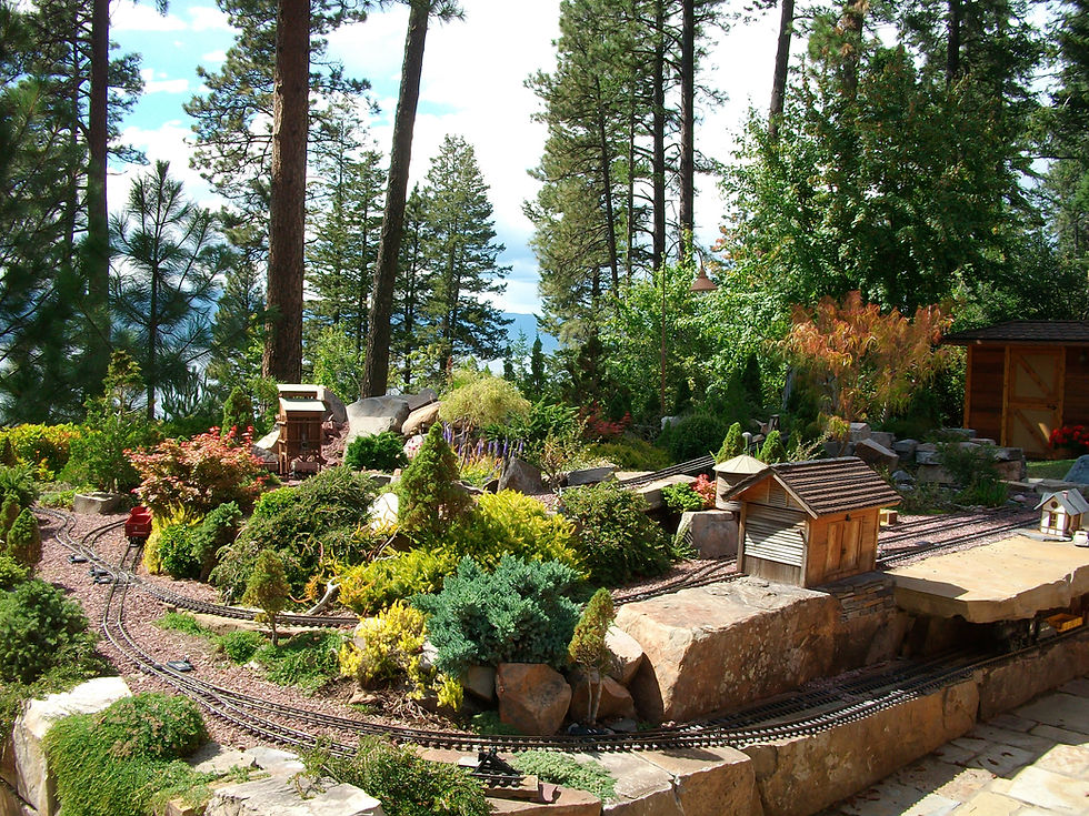
Mid Level Railways
I have used this term to describe any elevated roadbed built between ground and track level that is raised just off the ground a few inches as opposed to knee to waist high (or possibly even higher).
Why should you opt to build a raised railroad when a ground level one would seem to offer the simplest solution?
Firstly, raised roadbeds are considered to be easier to maintain and involve much less bending down which can be an important consideration for those who are not in peak physical condition.
Secondly, the higher the railroad the closer it is to eye-level and the better the vantage point for observing railroad operations. It is also easier to see and appreciate the model detailing which can sometimes be missed if viewing directly from above.
The third reason often advanced is that it this method makes it easier to compensate for difficult and varying terrain. If your line traverses several different elevations on its journey round your garden this may be the optimum solution minimising heavy groundworks.
An attractive raised bed railroad in the USA


A very overgrown railway.
Consequently, it is often more practical to install the roadbed even slightly off the ground, as shown in the adjacent image of a concrete substrate but this can also be achieved with all manner of materials.
Some enthusiasts always use tannalised wood (not creosoted wood which whilst cheap is no longer politically or environmentally correct and can sometimes react with the plastic sleepers) whilst others favour brick, stone or concrete blocks (heavy or light thermalite) to achieve the right working height.
Some methods are easier to work with than others and you may need to experiment to find the best solution compatible with your building skills.
A raised roadbed is also less susceptible to ground shift, erosion, flooding, frost damage, landslips, and burrowing animals (remember the dreaded moles) thus ensuring optimum reliability.
Penultimately, there is less opportunity for weeds and such-like to encroach on your line causing derailments making maintenance a lot less onerous.
And finally if you intend to run steam trains an elevated roadbed is virtually essential if only due to the constant need to add water and fuel your locomotive(s).

Embankments can be "earthed up" and planted with suitable ground cover plants to conceal unsightly bricks or concrete and help to stabilise the whole edifice (covered in Module: 21).
The construction methods employed for building mid-level structures are analgous to those outlined in the previous Low-Level section but built up to gain the extra height.
There are many ways to achieve this and some techniques are summarised below:

Earth or Rubble
The simplest, and possibily the least expensive way of gaining height is to use compacted earth ('dirt' for the benefit of our North American readers) or even builders rubble. You may be able to re-use 'spoil' removed from elsewhere on the layout avoiding the need to dispose of same and it avoids having to excavate a trench. The method is more akin to that on prototype railways where the roadbed is built upwards from ground level using layers of different materials to add stability and proper drainage.
On a garden layout it is customary to "top-off" the truncated pyramid with weather-proofed timbe of some sort such as marine ply, deckboards or floorboards. In fact, if you prefer to work in wood you can construct the embankment entirely in wood using short square posts with 4" x 1" spacers or stringers to keep everything secure although it is rather more difficult to reproduce curved sections.
One of the major advantages to this approach is the ability to make changes at a later date without too much upheaval.

Hypertufa Rock 5

Hypertufa Rock 4

Hypertufa Rock 1
Hypertufa Rock 5
Examples of Hypertufa
Bricks & Blocks
This builds on the shallow trench method described in the foregoing low-level section. The dugout channel is filled with a 2" - 3" layer of mortar which is laid with bricks or blocks (solid or light-weight thermalite) to the route and level required inserting mortar between each joint. The finished blockwork can be surfaced with roofing felt or alternatively, you can affix a wooden capping to achieve a wider trackbed and cover this with felt. Marine or Exterior Grade plywood is usually recommended, the life of which can be extended by covering with thick waterproof long-life stone covered roofing felt in grey or dark green. Decking Boards are also suitable for this purpose, easy to source from DIY outlets and often represent good value for money.
Depending on the final height it is prudent to add wooden guides to each side of the track-bed to reduce the possibility of a derailed train falling off sideways and being damaged.
These types of brick are mainly functional rather than pleasing to the eye and need to be concealed to prevent them from becoming an eyesore. You could bank up earth on one or more sides (and plant some fast-growing ground-cover, position rocks to camouflage their drabness or come up with an alternative to soften their appearance.
I also seem to recall a more ecologically friendly process for creating artificial or anthropic rock (known as “Hypertufa”) which dates back to ancient Mesopotamia. Man-made or Anthropic rock is produced from various aggregates bonded together using cement – concrete is probably the best-known example.
Hypertufa was endorsed on television by Geoff Hamilton, the well-known gardener, who used to present Gardener’s World in the 80’s and 90’s. At the time he was concerned about the depletion of the slowly precipitated natural limestone “natural tufa” and advocated porous hypertufa as a substitute for making alpine troughs, rocks and planters.
I believe that the classic recipe may have been:
-
5 parts Sphagnum or Peat Moss
-
3 parts Portland Cement
-
5 Parts perlite or Vermiculite
Geoff’s later version was:
-
1 part Sharp Sand
-
1 part Fresh Cement
-
2 parts Sieved Coconut Fibre Compost (Coir)
which no doubt reflected his campaign to also conserve our dwindling peat reserves.
The resulting tufa can be rather fragile until it sets properly but the revised 1:3 (cement to aggregates) formula may help to overcome this. The addition of polymer fibres, liquid acrylics and fibreglass also helps to increase structural strength and longevity as does the incorporation of small pebbles and crushed rock. Tufa dries to a grey colour but concrete dyes can also be added to create a particular stone-like appearance.
The tufa “mix” can be rendered onto old sinks, moulded in strong cardboard boxes, and even cast in a hole in the ground lined with polythene. For a more natural appearance the hypertufa can be painted with some form of organic matter such as yogurt, diluted fertiliser, stale milk, animal manure or even gravy to promote the growth of algae, lichen and moss.
You can find a longer section covering the myriad uses of hypertufa in the “Scenery” Module.
Timber
Uses timber beams instead of blocks or bricks but otherwise follows the first method. If additional height is required these can be screwed into 3” x 3” or 4” x 4” timber uprights set in Postcrete (other brands are no doubt available) for convenience (you can create your own mix if you prefer as it usually works out cheaper) or metal post spikes such as those made by Metpost. Be sure to use treated lumber (preferably pressure treated) and then given another coat of preservative just in case. It will rot at some time in the future but you don’t what to have to replace it every few years if you can avoid doing so.
The use of 50mm square recycled plastic uprights in lieu of timber might also be considered for this purpose as although they generally work out more expensive initially they could survive for 40 years or more saving you money in the long-term, especially if reinforced with mortar.
Concrete
This method uses loose-fill or pre-cast concrete to a greater degree than just “topping off” shallow trenches (see diagram). A much stronger concrete mix is traditionally needed (1 part cement, 3 parts coarse aggregate and two parts sharp sand) but it can be cast to virtually shape
I am currently using a slightly weaker general mix to envelop piles of broken brick and stone to create embankments and “mountain escarpments” – the render can be worked for quite some time before it sets allowing the surface to be sculpted to resemble rock face and scree. Eventually I hope to meld this artificial stone with natural rocks that were dotted around the garden but it might prove more difficult to blend the two forms than anticipated.
I have had to resort to mixing small batches for my own layout by hand and whilst this means that you can work at a slower pace there are sometimes differences in texture or shading due to my haphazard technique. If you are using a lot of concrete it may make sense to beg, borrow or even purchase (often for less than a week’s hire) which would achieve a better and more consistent mix. A small electric mixer is adequate for the task but make sure you hire or buy a 240v AC version as many intended for use on building sites run off 110v AC.
Large quantities of concrete inevitably mean bulky materials and while large bags containing 750 – 1000 kilos may work out cheaper they do require storage room which may not be close to your layout site. Apart from the potential damage to my car I find it more convenient to buy pre-packed 20 kilo bags (5 for the price of 4) from my local supplier as these can be stored close to the place where they are needed.
There is more detailed guidance on the creation of artificial rocks and mountainous escarpments in Module ...
Timber Shuttering
Where you are creating a trackbed above ground you will may need to install some form of temporary shuttering to hold the concrete in place whilst it sets. Flexible sheeting such as thin exterior plywood (25mm to 40mm thick) is ideal and even hardboard will do the job. I understand that these sheets are called ‘bender boards’ in the US.
HDPE Plastic Framework
For a more professional finish, and if you have lengthy runs to build, you might consider using flexible HDPE plastic formwork which speeds up the onsite preparation. The “Roadform” comes in two types – a straight section and a flexible section for curves – both in 12’ lengths x 2” wide x 4” (100mm) and 6” (150mm) in height. The latter is hollow and can be bent to form large radii.
Either form can be staked in position at any point along the form’s length and can also be stacked on top of each other to support higher builds up to 12” (300mm). The lightweight forms are durable and easy to clean allowing for many years of reuse.
TIP
Shape the concrete at the bottom of the post away from the post at a 45 degree angle to allow rain to quickly disperse

One such make is Plastocent - a light plastic (high-density polyethylene) formwork, easy to transport and store. It can be used with any support, in both straight and curving shapes and in horizontal, vertical and angled positions. The formwork can be easily cut and joined and are resistant to blows and oxidation. They can also be stacked for deeper pours and equipped with clamps for attachment to stakes. They can be removed as soon as four hours after the pour. Their texture prevents the concrete from sticking to their surface, resulting in good finishes, and making them easy to clean and re-use. Don’t forget to insert the short wooden fixing posts, if required, which should be treated on the ends with preservative to withstand the rain and damp.
"Large-Scale Concrete Laying with Shuttering"
Plastocent Formwork
Metal Formwork
Steel formwork can also be used for pouring concrete although they are not quite so flexible when it comes to making curves less than 6’ (2m) where plastic tends to ’have the edge” (unintentional pun but kept it in anyway).
For general advice on concrete formwork click the link
Release Agents
All formwork needs to be coated with a Release Agent (Soap Oil) before any concrete is poured to stop the concrete bonding to the formwork and then leaving scabs when the formwork is removed. This also helps to ensure the formwork stays clean so that it can easily be re-used again. If the actual finish of the concrete is not crucial you could probably get away with using engine oil.
A Premium Roadbed?
I have also recently read about a superior implementation using reinforced concrete beams (or wall blocks) and a topping called “Rubbercrete” (introduced as a model railway foundation by Model Rail Contributor Trevor Jones and described in the Autumn 1998 issue although it had previously been used for an unsuccessful experiment for insulating piggery floors). It now seems to be used in all manner of applications including gymnasium floors, children’s play areas and horse stalls but many potential users have encountered considerable difficulties obtaining the necessary rubber granules - parhaps car tyre recyclers might prove to be a source?
“Rubbercrete” is a fine concrete mixture using rubber and cork granules in lieu of sand and ballast. The mix is combined with a concrete bonding agent known as SBR which is a liquid, water-based styrene-butadiene polymer latex additive. It is claimed to improve the durability, water resistance and strength of cement mortars.
Advantages of using SBR (suitably diluted with water) include:
-
Improved adhesion and bonding
-
Easier to work with less water required
-
Reduced shrinkage and cracking on curing
-
Improved water resistance
-
Greater strength
-
Increased wear resistance
-
Improved freeze/thaw resistance
The cork particles are large bags of fine grade track ballast whilst the rubber ingredient is apparently derived from ground-up car tyres (and similar to granules used for surfacing children’s playgrounds).
The recommended mixture for 0 Gauge is:
-
2 parts (by volume) rubber chips or crumbs
-
2 parts each of fine, medium and course granules
-
4 parts cement
-
3 parts water mixed with half a part SBR
On 45mm Gauge layouts it may be better to omit the finer granules but I should emphasis that I have not yet tried the method. The mixture can be applied as a ¾” screed on top of a concrete or wood base and is reputed to accept pins easily.
Note that the SBR initially turns the mixture a bluish colour but this normally disappears as it dries. The water content is critical and it must not be too wet or shrinkage cracks are likely to occur as the mixture become dry.
When I came across this method the idea of using cheaper conventional PVA instead of SBR came to mind but it seems that this has a habit of turning pure white when it rains so perhaps not.
If sourcing the neccessary materials proves problematic you can always substitute the porous rubber based mats used for Equestrian and other purposes which come in rolls or sheets such as those illustrated below and are easy to cut to size:
Since undertaking further research, it would seem that rubber granules are not that easy to procure despite the obvious advantages to the planet’s environment. However, I did also come across several rubber paver products designed for use in children’s play areas. They are 500mm x 500mm square and 30mm thick and come in black, green, and red. These rubber play tiles weigh around 4.8 Kilos, cost about £7 each and can be fixed to surfaces using a rubber adhesive. I am not sure how easy they would be to cut but worth a look as they also appear to be manufactured from SBR and rubber granules.
I should stress that I have no experience of using this material myself, and have no connection with the company concerned, but it seemed to be worth a mention as a weatherproof substitute for cork strip used on smaller scale indoor railways.
Ladder Frame
This method would seeem to date back to 2002 and an architect called Bill Logan who worked on the committee to design a public display layout for the Franklin Conservatory in Columbus, Ohio. With his background he was keen to find a better way to install elevated roadbed than the "tried and tested" post and stringer method in use since the 1980's. He devised a simple solution which was less wasteful in timber, involve only basic tools and carpentry skills, to create a sturdy 'flexible ladder' support system which allows curved sections of virtually any reasonable radius to be easily achieved.
The method is fully decribed in the excellent Family Garden Trains™ primer article to be found on their website contributed by Paul race and Bill Logan entitled HDPE Flexible Railroad. There are 4 separateparts so I have provided individual links below:
Family Garden Trains also hosts several articles by Bob & Patricia Canfield, Las Vegas, Nevada who describe their own experiences using Bill's method to construct their own 0 Gauge outside layout called the "B&P" for obvious reasons. The following direct links will take you straight to the relevant web pages:
Splines
Another interesting method for creating a strong roadbed support is one which some readers, who have previously had experience in modelling smaller scale indoor railway, may already be familiar with. This involves the use of laminated splines of timber which are glued together to form a strong composite capable of being bent to make smooth curves which retain their shape when screwed in place. This technique is also widely used in the manufacture of structurally engineered timber products which are too big or unusually shaped such as curved beams.
A traditional timber spline is a thin (3/16" – 3/4" thick) vertical piece of wood, typically 8 – 12’ in length, made from pine, redwood, hardboard (Masonite) or similar timber which are spliced and glued together, using a strong wood glue, to create a sturdy, durable but flexible "stretcher length". A number of these individual "stretchers" (which are quite flexible at this stage) are then bent to the required radius and either screwed to each other, or to "spacer" blocks, to form a wider composite roadbed material which retains its shape.
If ripped 8’ x 4’ sheets of plywood are used for this purpose there is very little material waste unlike other methods involving “cookie cutting” individual curved sections as deck stringers.The downside is, that being fabricated from wood, they are still prone to deteriorate if used outdoors.
Splines are overlapped and glue together using strong yellow wood glue or PVC adhesive as appropriate, and held together with numerous hand clamps until thoroughly dry. This forms the centre spline to which additional double spline lengths are added both sides, one at a time, using wooden spacers. In fact the whole process is very similar to the “ladder” solution increasingly seen on high-level outdoor layouts but more lightweight and easier to form into curved stretches.
Using this method also makes it easier to introduce easements (see Module 9).
In recent years this long established technique has been ‘scaled up’ for use on outdoor garden railways and further refined,to resist the elements, by using lightweight and long lasting PVC or HDPE (High Density Polyethylene) materials in place of conventional wooden batten strips. These thermosetting polymers and thermoplastics have properties which make them much more suitable for use out of doors, are ultra- low maintenance and also tend to work out cheaper than expensive pre-cut timber.
The substitution of modern materials that are weather-resistant and impervious to chemicals, corrosion and frost. Individual splines can be made using strips/ laths of lightweight cellular vinyl PVC or HDPE which com ready-moulded into thin cross-sections - 5/8" (15mm) x 1.5" (38mm) x 8' (2.4m - 12' (3.6m) is ideal.
High level (Elevated) Railways
Many of the methods used to create Mid-Level Layouts are equally
applicable for building High - Level Layouts discussed in the next
segment.
In this section we are dealing with railroads that are positioned at
least 24" (600 mm) off the ground to achieve maximum visual
impact. This can involve quite a bit of work but you don't have to
tackle it all in a day. Take your time and make full use of any "free"
building materials that neighbours may be only too grateful to
dispose of (Always ask permission from the owner before
removing any suitable material from a skip).
If there is a downside to high level railroads it is probably that they are more expensive (both in time and materials) and can be more difficult to landscape.
Raised beds underpinned with walling blocks, sleepers or other supports are popular but you need to take care that they are safe and not likely to fall on some unsuspecting observer – it might be you!
Some modellers do spend a lot of time and inordinate effort recreating the physical landscape with tons of real rock, shingle, and earth whilst others make maximum use of existing wall and fences to attach a roadbed.
I have already mentioned the importance of having a proper viewpoint for maximum realism and this can sometimes involve building large physical structures such as raised beds or retaining walls underpinned concrete walling blocks, stone or wooden sleepers but you need to take care that they are safe and not likely to fall on someone.
Be sure to incorporate adequate drainage and use solid construction techniques as soil can be surprisingly heavy and a collapsing bank can be dangerous.
An existing wall can also provide a useful means of gaining height but avoid attaching your trackbed to a wooden fence panel as they have an undesirable tendency to blow down.

 |  |  |
|---|
_jp.jpg)
This Railway Channel video of a partly "raised" atmospheric narrow gauge railway set in Ireland shows what can be achieved by merging the upper levels seamlessly with the ground sections.
Raised Roadbeds
I have left the best 'til last, so to speak. The principle of raising up your track level substantially above ground can be taken to a more extreme extent by constructing a permanent raised area to encompass (and “show off”) the entire layout, or at least the majority of it, and complement the garden surrounding it.
This is likely to involve a lot of hard work (if you do the landscaping yourself) or considerable expense (if you hire a competent contractor to do it for you). It may be that this approach is the best solution for a difficult plot and may even involve less physical effort due where you are taking advantage of the prevailing terrain, such as a wall, steep slope or existing garden feature (such as a rockery) which can be incorporated to good effect.
We are very much in the realm of structural and civil engineering here where all manner of important considerations have to be taken into account, such as loading, strength, foundations, drainage, etc. You may also need to have regard to the concerns of your partner or family who may not necessarily welcome the prospect of the garden looking like a builder’s yard or rubbish dump for many months (if years!).
Having said that, and acknowledging the potential downsides, there is no reason why a more ambitious project should not prove to be the perfect solution.
You may well discover that the back of your intended layout inclines sharply and would require extensive shifting of earth to install a ground or even low-level layout. Far better not to fight nature and the prevailing topography but take advantage of the terrain. There are many layouts, especially USA mining or lumber lines, that derive much of their interest from trains hugging the rocks as they slowly climb steep grades to reach their camps in the mountains.
This recent "Family Garden Trains ™" Flagship article on the subject of building a raised platform railroad is particularly relevant and I thoroughly recommend using this free site on all garden railway topics:
Rockery
One way of enhancing the overall effect is to full integrate your layout into an existing garden feature such as a rockery or pond. If none exists already you might think it worthwhile to build one. Once again it can be a labour intensive chore moving heavy soil and rocks around the site and unless you have access to a plentiful supply of stones and rocks locally it can involve a significant financial outlay. At my garden centre 2 Kilo stones sell for about £3 – 7 each (and then you have to get them home).
However, a well-constructed rockery or pond will enhance the look of both your garden and your layout, especially where deep gulches, ravines or mountain hugging tracks are contemplated.
A rockery should be more than just a pile of stones. Each rock needs to be integrated into the soil and made to look as though it has occupied that spot for centuries alongside its fellow rocks.
The following images show what can be achieved with a bit of thought and careful positioning.
A
Traditional Methods
The most common method for high level implementation is to build on a raised base of 5" - 6" (130 mm - 150mm) wide flat timber planks (or decking board, gravel board, etc. is ideal) fixed to 75 mm - 100mm square (3" x 3" - 4" x 4" ) tanalised (pressure treated) wooden posts sunk into the ground or into proprietary heavy gauge metal spiked supports such a Metpost (other makes are available).
The precise distance apart at which posts should be installed can vary considerably according to the strength and weight of the board and the degree of curvature of the line. For straight runs of single track spacing every 1200mm (4') apart is normally adequate but for double track installations on tight curves 600mm - 900 mm (2' - 3') 24 - 36" is usually the norm and occasionally as little as 450mm (18") on really tight radius curves.
Try not to over-engineer but it is generally better to have too many supports than not enough.
Both techniques can be reinforced with concrete for extra strength. You can mix this yourself or purchase ready-made mixes designed for the purpose e.g. Postcrete, in order to simplify the process. It is a sensible precaution to slope the mortar away from all four sides of the post to aid water run-off as any contact between timber and ground will be an opportunity for rot.
For maximum rigidity (especially where multi-tracks are contemplated) it is also a good idea to attach longitudinal supports (known as "stringers") to each side of the uprights before fixing the top plank place.
Wooden boards will be continuously exposed to the elements so a secondary coating of wood preservative or even mastic is always beneficial. It is also advisable to fix some strips of roofing felt or other protective material to the top and sides for added protection and to create a rough surface for affixing the ballast.
A strip of metal or thin wood strip (slightly higher than the thickness of the board) screwed or nailed into the sides of the plank will help to keep both the underlay and the ballast in place and potentially prevent a prized locomotive or piece of rolling stock from coming to grief. If you go this route take care to ensure that the stringers are level. Special care also needs to be taken where two boards butt together and reinforce with longitudinal bearers where necessary.
Wood supports can have several advantages in that properly pressure-treated timber provides a firm and stable base and is fairly resilient in coping with wind and erosion. It's main downside, of course, is that timber, even when sealed and protected, against the elements will eventually succumb to wet conditions and need to be replaced.
A timber raised roadbed may look artificial and non prototypical but you can often conceal the structure with judicious planting of fast-growing shrubs.
Constructing a Roadbed to Existing Wall or Fence
It may be that you are contemplating attaching your roadbed to a pre-existing structure such as a wall, fence or garden shed. On balance this can often prove to be a costly mistake and lead to unforeseen consequences and much remedial work. If the wall is sound you may get away with attaching your roadbed using pressed steel metal brackets but if the layout eventually proves too wide or heavy it will need additional support. These brackets also have a propensity to rust which will leave your roadbed hanging precariously in free air meaning you will have to start all over again.
Trains rarely look convincing run against a background of stretcher bond even if painted a darker colour. You might also wish to have a scenic rocky background which might create damp problems and put even greater strain on the masonry.
At least a wall is preferable to a wooden fence which are notoriously troublesome and prone to rot or blow down at regular intervals. The usual advice is to ignore fences altogether but there may be certain circumstances where you might get away with it.
Modern Roadbed Materials and Methods
Plastic Wood Composites
I have noticed that several modellers writing in the model press and related forums have described using various types of Recycled Plastic Wood (or Plastic Wood Composite as it is generally known) in place of timber to very good effect.
These versatile new materials are practically impervious to the weather and insects, do not rot, don't need protective treating, reduce our carbon footprint, and will last a lot longer than wood (50+ Years is claimed – and even then, they can be recycled!).
At the moment they tend to be much more expensive compared to traditional timber but if longevity and low maintenance is a primary requirement the financial outlay may be justifiable.
The products of one UK manufacturer, Filcris Ltd., are featured later in this Module as they produce recycled plastic products specifically to cater for the garden railway enthusiast. Other trade products suitable for this purpose may also be available so check your local DIY store and online for sources.
Other Novel Solutions
Some modellers (especially in the USA) have experimented with other more novel approaches to off-ground elevated tracks including thick rubber tiles, zinc trays, uPVC soffit board and even square profile soft PVC downpipe which has the added benefit of being waterproof. While these materials may be more durable they tend to work out more expensive, and white PVC is not necessarily UV resistant turning brittle when exposed to sunlight although the downpipe comes in at about £2 – 3 per metre.
PVC downpipe or trunking can also be used for upright supports. They can be filled with concrete for greater strength and rigidity if required.
The main problem with these alternatives is that they are more difficult (if not impossible) to bend round curves. However, if you experiment with large diameter soft PVC piping (40mm diameter is about right) it will curve a lot more easily in much the same way as a wooden support. It also has the advantage of being flexible in the vertical plane enabling you to represent your railway in 3D form giving you a much better idea of how things will eventually look. If you prefer something a little bit more robust why not tie three lengths of PVC piping together using cable ties.
You will need to cut the square profile PVC to suite the radius of your curved track and join each piece together using a pipe offcut as a joiner which is “coerced” into the end of each section and glued with PVC solvent. The pipe can also be used to construct upright supports but need to be filled with sand or concrete to add rigidity.
HDPE (High Density Polethylene)
Another construction technique that seems to be increasingly popular is the use of recycled HDPE (high density polyethylene) often referred to as “plastic wood”. This material has been highlighted in a previous section of this module as a suitable material fro ladder frame roadbed supports.
This is not unlike the Filcris Product referred to earlier and whilst there do not appear to be that many outlets in the UK there are a number of specialist suppliers. One of these is Centriforce who supply recycled HDPE planks and profiles under the name “Duraplas”. The difficult part is often to ”rip down” the sheet material into usable sections but if you can find the material already cut into 140mm (composite decking) or 185mm strips (Fascia Board) so much the better.
Composite board lengths are sold under the trade name Trex™ in the UK and USA but I have no doubt that other brands may be available. These are not as flexible as HDPE board due to their timber content but might be suitable for wider radius curves.
Like most good products the material is not cheap but is extremely durable, impervious to most things, relatively easy to work and should last quite a while (at least 4x longer than conventional timber).
Another environmental benefit from using recycled HDPE is that it is manufactured from 100% recovered plastic sourced exclusively from materials which otherwise would end up in landfill, exported (e.g. milk bottles and containers) or as we have recently been reminded, polluting the world’s oceans.
If you are interested in the potential for these solutions (especially the flexible HDPE Roadbed technique which does go around corners) you may find the following references of particular interest and whilst the articles describe an O Gauge layout the basic principles are capable of being applied to any scale or gauge:
Click this link to return to the earlier "Ladder Framework" section:
Pre-casted Concrete Deck Blocks
Raising the trackbed to the required level necessitates some form of stable support. This can involve the laborious digging of post holes, mixing concrete and pouring footings to erect posts and protect them from direct contact with the ground – so minimising the risk of rot or damage by vermin.
A relatively new innovation that could have an application in simplifying the construction of garden railways is the Pre-cast Concrete Deck Block (sometimes referred to as Deck Piers) which can be used as a stable structure to support your track base.
Due to their small footprint these ‘pre-cast foundation blocks’ are only capable of supporting relatively light loads when set on a gravel bed but could be ideal for garden railways and best suited to low or near to ground decks.
Moulded into the top of each pier are wide slots designed to seat 47mm-50mm (2”) wooden joists to which your track bed can then be secured (See attached image). Some piers also come with a square moulded central recess to accommodate 75mm (3”or 100mm (4”) treated posts to create an even higher elevation if required. If the blocks are set in a bed of compacted gravel (or even better set below the surface and back-filled - although this does require a modicum of excavation) they can eliminate the need to dig deep post holes and mixing and pouring concrete altogether whilst still remaining firm.
For additional strength and stability they can still be ‘concreted in‘ if appropriate to spread the load and minimise lateral movement.
There are a number of versions available but you may only find one example at your local builders’ merchant or garden centre. The following types may be more commonly available:
Handi Blocks
This fairly recent innovation is the "Handi Block" from Featherlight Precast Products Inc. in Alabama, USA and whilst I have seen similar products in DIY supermarkets in the UK they tend to be made of heavy concrete.
Handi-Block is an ultra-light weight cellular concrete deck pier which can be used as alternative to traditional concrete piers when building raised platforms / decks for garden railways. The unique construction materials used offer extreme strength and durability combined with reduced weight which allows the job to be done with a lot less effort and strain on your back.
Handi-Block is 3 times lighter than traditional concrete block, has a high load bearing strength, increased stability and is designed to be used with 2” × 4”, 4” ×4” and 6” ×6” timber. The unique materials in Handi-Block allow for drilling and sawing with standard woodworking tools (to accommodate other dimensions) making it a suitable support pier uprights or lateral boards.
DekBlok™
These trade-marked Concrete Piers (from Supreme Concrete) are an ingenious product that can eliminate these laborious steps as there is no requirement for wet concrete or post excavations.
Unlike Handi Blocks these are manufactured using conventional heavy concrete to provide maximum stability when laid on solid ground. All timber is protected from contact with the ground minimising the risk of rot or damage.
Each DekBlok measures 300mm x 300mm x 100mm. The central recess in the unit is designed to accept 75mm (3”) or 100mm (4”) timber posts whereas the four way slots can accommodate standard 50mm (2”) support timbers.
More Modern Materials
Recycled Plastic Wood
I have already mentioned Fulcris Ltd., based in the UK, as a specialst supplier of useful products for the garden railway modeller. They are manufactured from recycled plastic and specifically designed for use by garden rail enthusiasts. These include recycled plastic sheets which can be used just like plywood to make a sturdy track bed that will last many years with these additional benefits:
-
It will not rot.
-
It will not delaminate
-
It will not warp when it gets wet.
-
It can be accurately cut on their CNC router to your design.
-
Or you can choose from a wide range of stock sizes.
There is now a complementary Ladder Frame System which
-
comprises a wide range of components to choose from.
-
Is also rot proof and maintenance free.
-
Is flexible but strong and tough.
-
Can easily conform to any design.
The only downside would seem to be the relatively high cost but if you feel that the investment would be worthwhile check them out by clicking the Filcris link below or visit their website direct using the web address (you may have to navigate the site - usually by selecting "Garden" and then "Garden-railway-products as the content tends to vary with time:
http://www.filcris.co.uk/products/garden-railway-products
Further Aspects of Raised Roadbeds
It is virtually impossible to cover all aspects of elevated railways in this manual but here is a quick wrap-up of other things to consider when embarking on such a proect. The principle of raising up your track level substantially above ground can be taken to a more extreme extent by constructing a permanent raised area to encompass (and “show off”) the entire layout, or at least the majority of it, and complement the garden surrounding it.
This is likely to involve a lot of hard work (if you do the landscaping yourself) or considerable expense (if you hire a competent contractor to do it for you). It may be that this approach is the best solution for a difficult plot and may even involve less physical effort due where you are taking advantage of the prevailing terrain, such as a wall, steep slope or existing garden feature (such as a rockery) which can be incorporated to good effect.
We are very much in the realm of structural and civil engineering here where all manner of important considerations have to be taken into account, such as loading, strength, foundations, drainage, etc. You may also need to have regard to the concerns of your partner or family who may not necessarily welcome the prospect of the garden looking like a builder’s yard or rubbish dump for many months (if years!).
Having said that, and acknowledging the potential downsides, there is no reason why a more ambitious project should not prove to be the perfect solution.
You may well discover that the back of your intended layout inclines sharply and would require extensive shifting of earth to install a ground or even low-level layout. Far better not to fight nature and the prevailing topography but take advantage of the terrain. There are many layouts, especially USA mining or lumber lines, that derive much of their interest from trains hugging the rocks as they slowly climb steep grades to reach their camps in the mountains. These railroads feature steep grades but the visual appeal cannot be under-emphasised.
Rockery and/or Pond
One way of enhancing the overall effect is to full integrate your layout into an existing garden feature such as a rockery or pond. If none exists already you might think it worthwhile to build one. Once again it can be a labour intensive chore moving heavy soil and rocks around the site and unless you have access to a plentiful supply of stones and rocks locally it can involve a significant financial outlay. At my garden centre 2 Kilo stones sell for about £3 – 4 each (and then you have to get them home).
However, a well-constructed rockery or pond will enhance the look of both your garden and your layout, especially where deep gulches, ravines or mountain hugging tracks are contemplated.
A rockery should be more than just a pile of stones. Each rock needs to be integrated into the soil and made to look as though it has occupied that spot for centuries alongside its fellow rocks.
Be careful with ponds though - it can be a 'heart-stopping' moment if you see your prized locomotive and accompanying cars derail and hurtle into the waters below:
In fact, the LGB Stainz locomotive is actually capable of running under water but the actual video of this scene is no longer available so I substituted the above. These pond scenes are a little more restful:


Describe your image
The following images show what can be achieved with a bit of thought and careful positioning.


Low Walls
If you possess the necessary brick laying skills (and even if you don’t) a popular way of building a raised bed
is to construct a low single skin brick/stone retaining wall around the layout perimeter or a parallel pair of low walls to support an elevated stretch of line.
Provided you lay the bricks on a solid foundation (at least 6” (150mm) of concrete is recommended for even
the lowest wall) it is perfectly acceptable to build up to a height of around 2’ (600mm) using a simple bond
and a 5:1 mortar (5 parts builders sand and 1 part cement). You can also incorporate a plasticiser which makes the mortar more malleable for longer. Apparently, washing-up liquid works just as well and probably works out much cheaper. Above 2’ you will probably need a much more solid self-supporting structure which is best left to experts.
Remember to incorporate drainage gaps in the base of the wall to allow any excess ground water to seep
away into a suitable soakaway.
There are numerous online websites offering advice on how to build a wall such as:
Even if the finished result does not look as professional as it might you will have the satisfaction of knowing
that you did it yourself and that any imperfections can readily be attributed to “rusticity”.
Retaining Walls
Walls higher than 2’ or so are likely to require proper concrete footings and substantial retaining walls. A retaining wall is a structure designed and constructed to resist the lateral pressure of soil when there is a change in ground elevation that exceeds the angle of repose of the soil. It should also have proper drainage
to ensure that excessive groundwater can drain away and relieve any hydrostatic pressures on the wall.
Unlike house walls, the tops of garden walls are very exposed and absorb rainfall which can freeze and damage the underlying brickwork. One solution is to fix engineering bricks, or better still overhanging
“capping” stones which will slow down the rate of soakage.
This video shows you how to build a simple but solid dry retaining wall using special blocks:
A retaining wall is even more susceptible to frost damage as it permanently in contact with damp soil so it is a good idea to line the back of the wall with plastic sheeting and incorporate a damp proof course. If you are inserting drainage outlets make sure that the polythene is tightly sealed around them.
Advice on building walls is readily available on the internet.
There are several types of retaining wall including Gravity; Piling; Cantilevered and Anchored depending on the site, the engineering complexity and intended purpose of the wall but Gravity Walls are the principle method used in a garden.
A full explanation is to be found on Wikipedia by clicking this link.
Gravity Wall
An example of a gravity wall commonly found in a garden environment is the substantive edifice of heavy timber railway (railroad) sleepers either embedded vertically in the ground or arranged longitudinally. These are equally suitable for low, medium or high-level layouts. The sleepers illustrated below are actually manufactured from concrete although wooden sleepers are more conventional and easier to obtain.

Try to avoid using second-hand recovered sleepers that are heavily contaminated with oil based substances like creosote which can be hard to remove from skin or clothing and may be corrosive.
Nowadays the same effect can be achieved by using timber effect concrete sleepers, some of which are quite convincing as you can see from the associated images. Benefits of the latter approach include:
-
Free Draining
-
No foundation required
-
Take up minimal space
-
Zero maintenance
-
Don’t warp, rot or splinter
-
Fire-proof
-
Labour efficient
-
Structural integrity
For tips on solid retaining wall construction visit the Family Handyman website.
Timber
Another alternative to railway sleepers (or similar heavy lumber sections) is timber construction using pressure-treated wood. Combing the internet (especially the images) can provide you with plenty of ideas to employ in your own garden – especially where terraces are contemplated.


Another alternative to railway sleepers (or similar heavy lumber sections) is timber construction using pressure-treated wood. Combing the internet (especially the images) can provide you with plenty of ideas to employ in your own garden – especially where terraces are contemplated.
WoodBloX
There are also pre-designed, made-to-measure, pre-cut kits, such as WoodBloX, where all the hard work has been done for you and where the product is guaranteed at least 15 – 20 years or more. The pressure-treated blocks come in 5 sizes and are light and easy to assemble on virtually any ground using circular plastic dowels which expand in situ. The company also offer a free design service. The only off-putting aspect would tend to be the cost but in terms of convenience and simplicity this solution would appear to have a lot going for it.
Watch this video to see how easy they are to use or visit the WoodBloX website.

An example of a L-shaped bed formed using Woodblox - just imagine an end to end garden railway layout in place of the plants
Terraces
On sloping ground, where a low retaining wall may not be able to adequately cope with the forces exerted on it, consider sloping the initial wall and then building raked terraces at intervals up the slope. The layout can be designed in such a way as to utilise these terraces to good effect and can improve both the interest and “viewability” of your layout.


Block Walls
If you don’t feel that confident building a brick wall there are a number of alternatives that make the job a bit easier. The first is to use dense pre-cast concrete blocks (approx.(h)215mmx(w)100m(l)440mm) commonly used by the building trade and work out relatively inexpensive. Their appearance leaves something to be desired and would benefit from concealment with some form of natural rocks or greenery.
You can even source more sophisticated interlocking concrete blocks (a bit like lego blocks) which make the
job even more straightforward although these can be very heavy to lift or manoeuvre unaided. Once again concrete blocks can look austere and need camouflaging to fit in with a garden environment.
Another option, and more attractive alternative, is to use reconstituted stone wall building blocks available
from most garden or builders outlets. These are aesthetically pleasing, easy to lay, often require no mortar,
and come in a range of traditional and contemporary finishes.


Bob Uniack’s Sierra Grande & Pacific Railroad (Video Courtesy of LSOL)
Bob Uniack's delightful Sierra Grande & Pacific Railroad 15 years in the making in a rural setting and featuring logging operations. The line originally featured mainly Aristo-craft 1:29 Scale components but now Bob has switched to 1:20.3 Scale for greater realism and runs Bachmann Spectrum only.
Watch all the way to the end of the video and see Bob's live steam shop where he made LARGE scale trains!
ADDITIONAL REFERENCE MATERIAL:
An article from the Large Scale central Forum employing unusual materials – at least 8 chapters)
Building a Raised Platform (Timber) Family Garden Trains
Port Orford Coast Railway - Elevated Layout (PDF)
This is a great example of a high-level layout built to a professional standard. Every step in the development of the line has been meticulously logged by the owner and comes highly recommended by enthusiasts who have enjoyed following the saga. This article has to be downloaded as a PDF document from this weblink:
More Raised Roadbed Ideas
Detailed guidance on spline construction:
Videos
I will end this module by highlighting a number of videos from around the world that demonstrate the variety of layouts that can be created by paying attention to your foundations.
Finally a raised layout showing the benefits of a raised roadbed on which to run your trains:
General Reference Sources
General basic construction advice including a useful decision table.